This thread has been locked.

If you have a related question, please click the "Ask a related question" button in the top right corner. The newly created question will be automatically linked to this question.

TPS53631: Start-up fails at lower temp

Part Number: TPS53631

Hello,

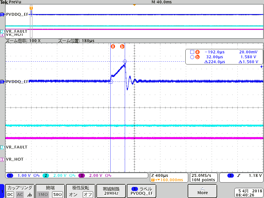
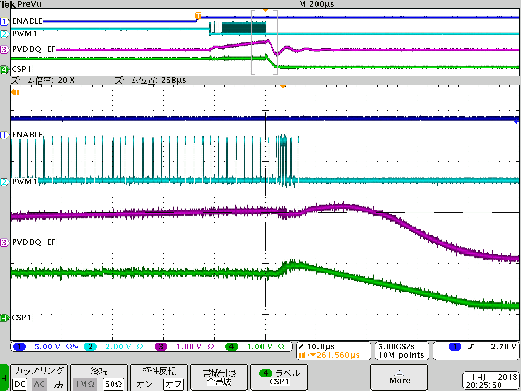
TPS53631 PWM stops at start up in lower temp test. The below is the waveform when issue happens.

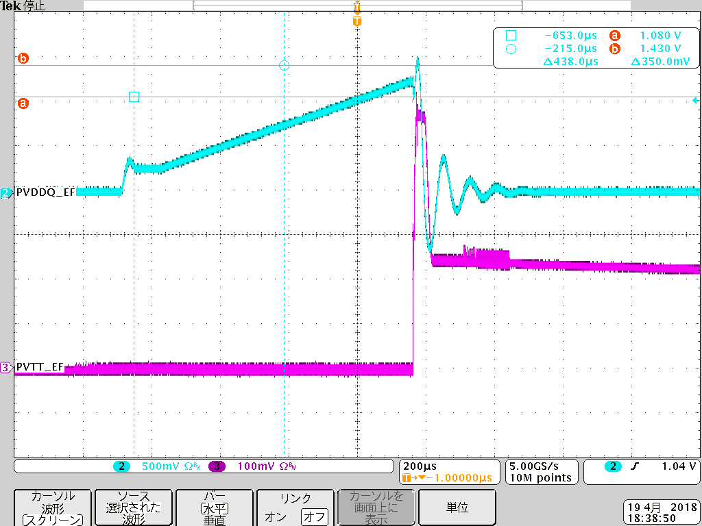
Before stops, Switching frequency seems to become faster and CSP voltage increase. 

This power supply is for DDR memory. VTT regulator enabled at when switching frequency is faster.

In this case, VR_FAULT didn't assert. MOSFET is CSD95372. I need to solve this issue. Please let me know why TPS53631 works like this?

Best regards,

Toshihiro Watanabe

  • Hi Toshihiro,

    Can you hook into the PMBus pins and get a snap shot of the fault window on start-up please? That can help give us some insight into what's happening during this error.

    Also, when you say that the VR_FAULT# pin didn't assert, does it remain high the entire time or is it stuck low? Finally, does the VR_RDY signal ever go high during startup?

    Thanks,

    Carmen

  • Hello Carmen-san,

    The below is the PMBus condition when issue happens.

    VR_RDY goes high once.

    The VR_FAULT is High stable.

    Best regards,

    Toshihiro Watanabe

  • Hi Toshihiro,

    Thank you very much for sending that data over. I'm reviewing it with some other apps engineers and will get back to you as soon as I can with feedback.

    Cheers,

    Carmen

  • Hey Toshihiro,

    Can you please change the start-up slew rate to a slower value than what it's currently set for? If the issue goes away at a slower speed it would help find root cause.

    Also, if you can share the schematic with me that would be helpful too as I can check for anything that may be awry. Finally, a scope shot with VOUT, CSP1, and TAO on it would shed light into what's going as well.

    Thanks,

    Carmen

  • Hello Carmen-san,

    I sent the schematic offline. Please check it. Regarding your requests, I will let you know later.

    Best regards,

    Toshihiro Watanabe

  • Hello Carmens-san,

    We could measure VOUT, CSP1, and TAO waveform which result is attached. Slew rate measurement would be update later.

    Best regards,

    Toshihiro Watanabe

  • Hi Toshihiro,

    I emailed you some notes about the schematic you sent me. They might help resolve the issue. But testing at a slower slew rate could help out too so be sure to run that test still. In order to keep things organized we can switch to email going forward and leave E2E if you. If so, click resolved and we'll take this offline otherwise we can communicate on here.

    Cheers,

    Carmen
  • Hello Carmen-san,

    We tried slower slew rate power on but the issue occurs. Slew rate is changed from 20V/m to 5V/m.

    So far, slower VTT power on slew rate helps for this issue but we want to confirm what makes TPS53631 stop.

    Withouth knowing the mechanism of stop, we can't determine this slower VTT slew rate is truely works or not. 

    We are working the change of your advice. It is only done at room temp. Not sure how to work in lower temp.

    Best regards,

    Toshihiro Watanabe

  • Hello Carmen-san,
    After change compensation circuit, there is no issue happens at -10C in 10 times power cycles.
    It would be helpful if we can know what is happening then stops.
    There is a fault information, Slower slew rate power up doesn't work, compensation circuit modification works and slower VTT power up helps.
    I guess TPS53631 was working with fewer phase margin, lower temp reduces phase margin fewer and VTT power-on triggers oscillation. Vout OV and UV faults would guess due to oscillaton happens.
    If my guess is correct, proper phase margin setting and fewer VTT turn-on shock prevent oscillation.
    Best regards,
    Toshihiro Watanabe
  • Hi Toshihiro,

    If the compensation changes have fixed the start-up issues then I would say the original root cause was likely due to poor phase margin getting worse over temperature. If stability was marginal to begin with then oscillations or overshoot could happen on startup causing failures.

    If you have the ability to measure bode plots taking one at room temp and low temp with the old and new compensation in place would show the shifts in the gain and phase curves.

    Thanks,

    Carmen

  • Hello Carmen-san,
    Thank you for your comment. The customer asks if TI can do bode plot simulation. I ma not sure we have a model.
    Do we have an environment to simulate TPS53631 bode plot? If yes, please let us discuss about this. If no, I will tell the customer it is difficult due to the environment matter.
    Best regards,
    Toshihiro Watanabe
  • Hi Toshihiro,

    Unfortunately there is no Simplis model of the TPS53631 available to run simulations on. If the customer has a network analyzer they can generate their own bode plot using the procedures in the app note below.

    www.ti.com/.../snva364a.pdf

    Cheers,

    Carmen