This thread has been locked.

If you have a related question, please click the "Ask a related question" button in the top right corner. The newly created question will be automatically linked to this question.

TPS61221: Extending soft-start/limiting inrush current for TPS61221

Part Number: TPS61221
Other Parts Discussed in Thread: TPS61291

Hello,

We have a small, low-power device with a sub-1GHz transceiver and MCU (CC430F5xxx series), where power is supplied from a coin cell (CR2032 and/or CR2450) battery. The device sleeps most of the time and does not require a regulated output, and regulator is only enabled when a regulated rail is desired (chiefly RF communications) or when battery voltage is too low to squeeze some more battery life out of it. Whenever the regulator is not enabled, the device is powered directly from the coin battery thanks to the pass-trough capability of the TPS61221.

Whenever we enable the voltage regulation, the high inrush current causes the battery voltage to dip steeply due to the high ESR of coin batteries, which causes the output voltage to dip with it and causes a brownout event and erratic behavior. We have tried adding large bulk capacitors parallel to the battery and an 680uF battery solves this issue and a 330uF battery alleviates it to an acceptable level. However, these bulk capacitors are larger than we can accommodate in the product, therefore we would like to be able to combine it together with a method to reduce the inrush current. According to the answer to a previous question on this forum, application note SLVA307B is not applicable here due to the pass-through capability. We have done some quick tests with the soft start extension circuit proposed in SLVA307B just to see, however it drove the regulator out of stable operation.

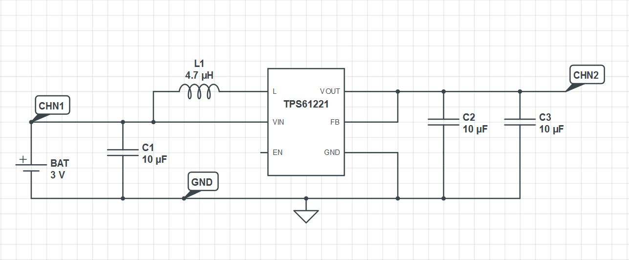
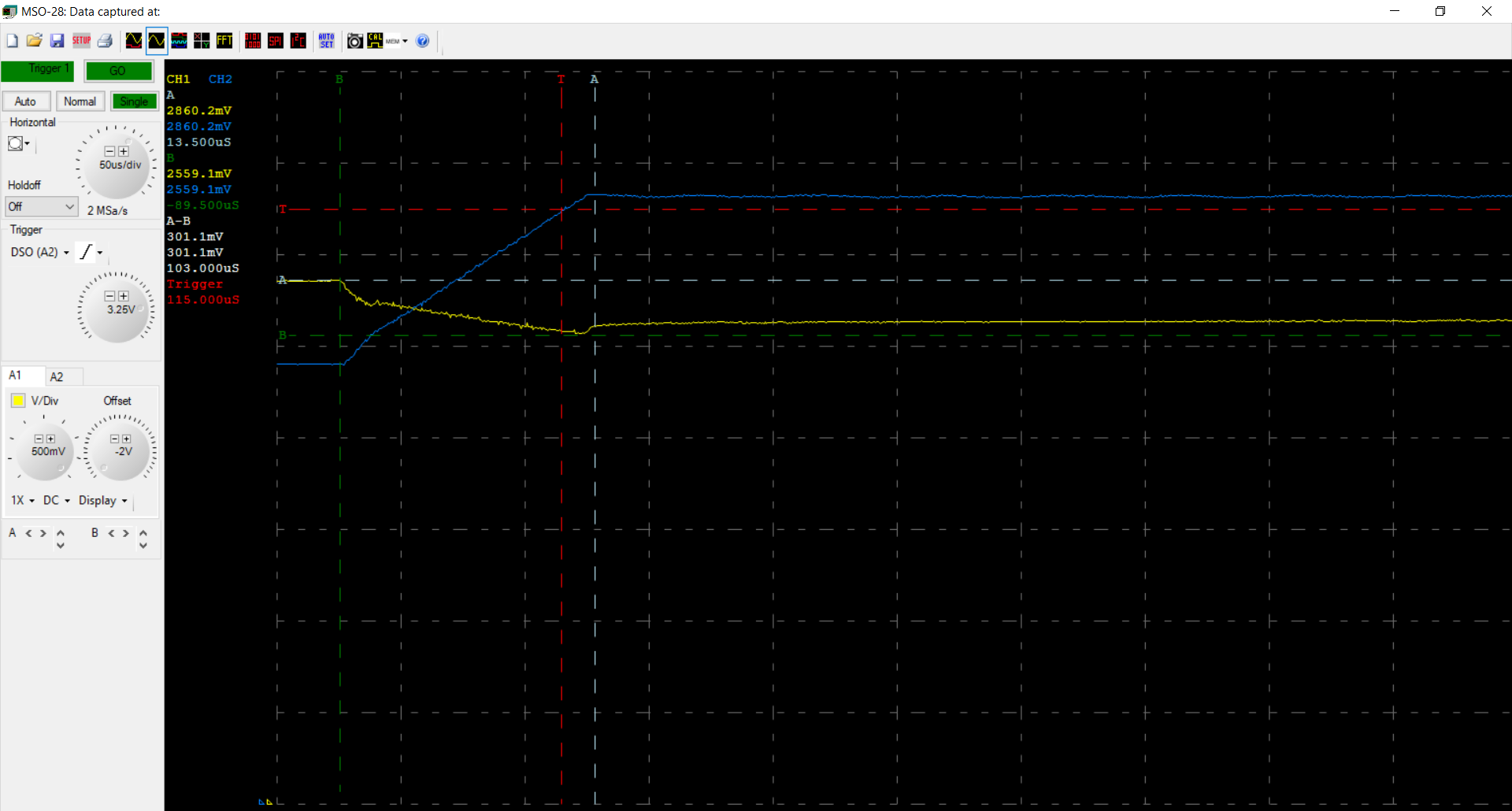
Below are a schematics and the measurement results with and without bulk caps, and with the soft-start extension circuit:

Voltage measurements at the probe points marked on the schematic:

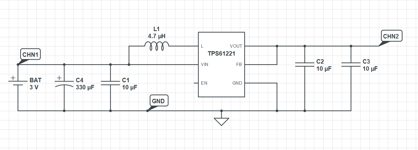
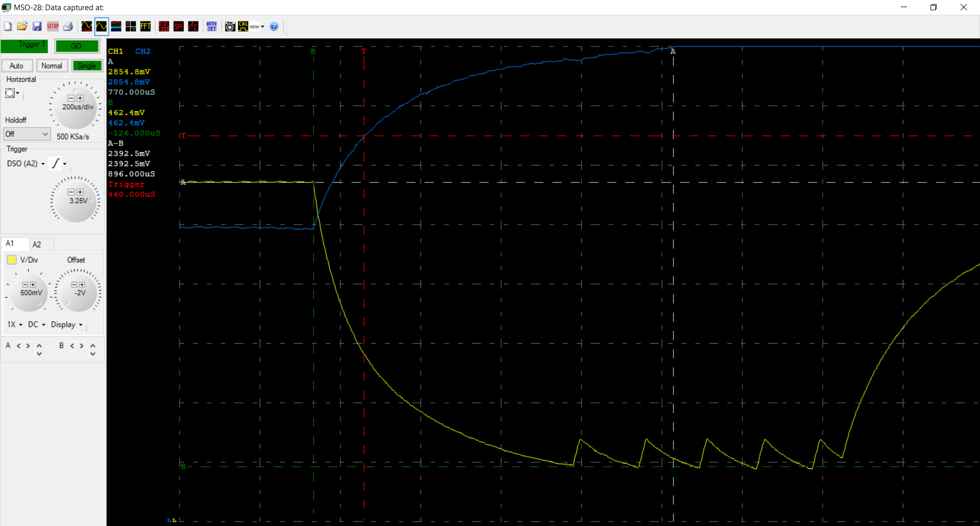
When a 330uF tantalum bulk capacitor is soldered parallel to the battery:

Voltage measurements at the probe points marked on the schematic:

And finally, measurements with the soft-start circuitry from SLVA307B added to the feedback loop:

Voltage measurements at the probe points marked on the schematic:

To summarize, we are looking for a method, preferably without adding or changing any ICs, to reduce the inrush current/extend the soft-start operation of TPS61221, so we can use it together with small coin cells without the need for excessively large bulk capacitors. We are more than open to any suggestions for alternative ways to approach this issue as well.

Cheers!,

İsmail

  • The expert for this part will reply you within 2 days.
  • what is maximum output current for the MCU? you can try
    1. reduce the output capacitor to 10uF or 4.7uF.
    2. a schottky diode from battery to VOUT.
    3. increase the input capacitor.

    i thinks TPS61291 is a better solution for this application.
  • Thank you for your reply, I think I have omitted some important information in the original post.

    The measured maximum current draw of the application board is ~30mA. According to our preliminary measurements, maximum inrush current hits ~200mA when boost converter is enabled.

    The schematics show only the regulator circuitry for brevity, however output of the regulator is connected to an application circuit and the total capacitive load on it is ~60uF on top the regulator output capacitors.

    Increasing input capacitors significantly alleviates the issue, however they are adding considerable bulk so I'm mainly trying to reduce the size of additional capacitors required at the input.

    I will take a closer look at TPS61291, thank you for your suggestion. However, we have a stock of TPS61221 we would like to use before switching to a different part, so I am still interested in solutions for that.

    Regards,

    İsmail

  • Hi
    60uF output capacitor is real large. is it possible to reduce the output capacitor? the issue is actually caused by charging large output capacitor.

    by the way, the external soft start circuit doesn't work because the circuit need external feedback resistor.
  • Hello,

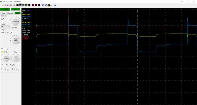
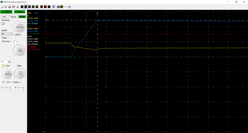
    I've tried reducing the capacitive load by 22uF to ~40uF by removing certain parts from the application board, however I've started to see significant start-up overshoot to 3.7V, which is above application circuit operation conditions and causing components to malfunction/latch-up. I'm attaching measurement results below. To be honest, I wasn't expecting this since there is still more than enough output capacitance, do you have any suggestions? I will play around more with capacitive load values but I would like to be able to understand what's going on. I don't know if there is a reasonable external solution for the start-up overshoot.

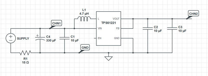
    Schematic: (Load connected to this has a capacitance of ~40uF as opposed to ~60uF of the results in the original post, R1 is there to emulate the ESR of the battery while circuit is supplied from a desktop power supply)

    Regulator startup behavior when toggled periodically, notice the 3.7V overshoot peaks when first enabled:

    When zoomed into the overshoot peak during startup:

    Thank you!,

    İsmail

  • i didn't see this kind of behavior before. could you share the layout? what is part number of the inductor?
  • The inductor model is Taiyo Yuden NR3015T4R7M, I am attaching the layout for the regulator below as well. We will redo the measurements on a separate board to make sure its not caused by faulty components.

    Layout:

    Thank you!,

    İsmail

  • the layout is good.
    please try to check if you can find issue in two more other boards.
  • HI
    I closed the thread as no feedback. it open again if you reply it.