This thread has been locked.

If you have a related question, please click the "Ask a related question" button in the top right corner. The newly created question will be automatically linked to this question.

TPS54340: not able to startup under load

Part Number: TPS54340
Other Parts Discussed in Thread: LMR14050

Support Path: /Product/Development and troubleshooting/

I am using the TPS54340 to provide +12V, 3A with a Vin of 14-18V.

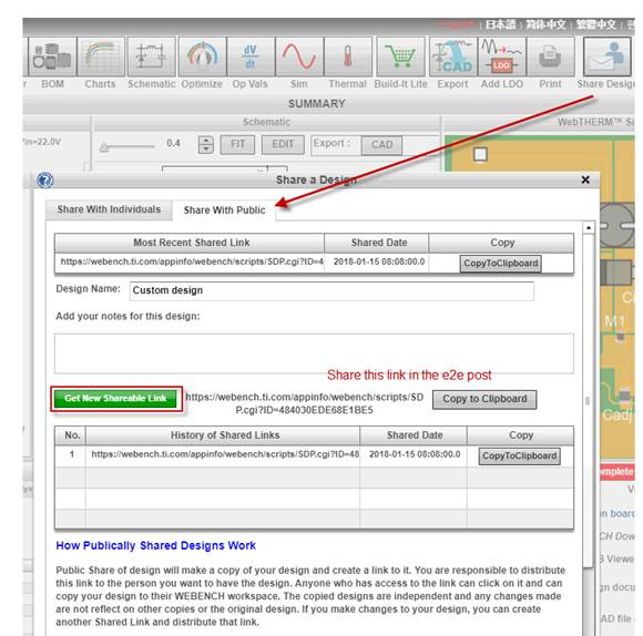
I used WEBDesigner and built the 5 PCBs using the design.  They marginally work when starting up with load of 1-3A.

The layout is text book.

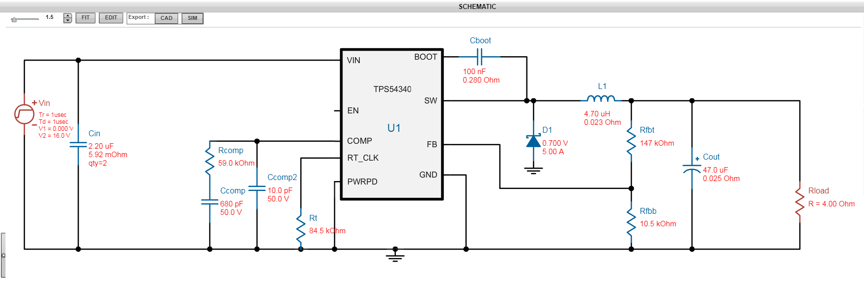
The symptom appears to be output skipping - I added ULVO to not start until I am above 14.5V - that help get the plots provided.  

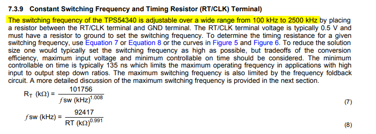
The datasheet calculations suggest a max Freq of 330 kHz but the WEBDesigner provided 84.5k for ~ 1MHz. 

I suspect it is frequency related but don't know why WEDDesigner can be so misleading.  FYI if you put the design example in the data sheet into WEBDesigner it violates the rules also.

Best,TPS54340 test result.pdf

Adrian

  • Hello Adrian,
    I will forward your question to Webench team.
    Regards
    Brani
  • Hello Adrian,

    Could you please let us know that whether you are using the same board schematic & BOM components that as of  WEBENCH schematic?

    Please share the design link with us using 'Share Design' option on WEBENCH as shown below.

    Kindly note that the maximum frequency of the device is 2.5MHz, Please refer to the below points in the datasheet  as shown below.

    Thanks & Regards,

    Praveen Badiger

  • Hi Praveen,

    I tried a few different input options (Vmin/Vmax a few volts difference) since the original schematic and build.

    Don't seem to be able to reproduce the exact component list as the original for some reason.
    The link is:
    Rt is slightly higher than the original and compensation is slightly different.
    I re-read section 7.3.9 when the design provided by WEBENCH did not work .  WEBENCH  appears to violates that section - a design optimized for size that violates the component design rules is not a design - agreed?
    Best,
    Adrian
  • found the original web design
    webench.ti.com/.../SDP.cgi
    also the requirement for regulation requires the max frequency to be step down from 1 to 8.
  • this issue is not resolved

    please explain equation 10 in the data sheet with respect to the max frequency allowed from equation 9.
    WebDesign sets the frequency to ~1.1MHz while equation 10 states under digital selection to maintain current regulation it needs to be ~ 300kHz.

    Which is it?
  • another related question related to output current at start up.
    when powering up at heavy loads the data sheet states:

    At heavy loads, the minimum input voltage must be increased to ensure a monotonic startup. Equation 2 can be
    used to calculate the minimum input voltage for this condition.
    where
    • D(max) ≥ 0.9
    • IB2SW = 100 μA
    • TSW = 1 / Fsw
    • VB2SW = VBOOT + VF
    • VBOOT = (1.41 x VIN - 0.554 - VF / TSW - 1.847 x 10³ x IB2SW) / (1.41 + 1 / Tsw)
    • RDS(on) = 1 / (-0.3 x VB2SW^2 + 3.577 x VB2SW - 4.246) (2)

    Assuming Fsw is in Hz as it is elsewhere in the document VBOOT is dominated by VF / TSW and VBOOT is negative, and then you get a negative RDSon.
  • Hello Adrian and Praveen,

    We have been in touch via email in order allow nonpublic information to be exchanged. TI has determined that the DS needs work:
    The equations shown above are primarily for low dropout with low input voltage high frequency. The datasheet does not limit the range for these equations allowing obviously incorrect results from calculations.

    As suspected, the units for FSW while not listed but are MHz. This can be seen by looking at other datasheets in the TPS54k family.
    As for Webench support, Webench does not support simulation for the actual conditions under which this part is being used. Input voltage cannot be set to ramp slow enough and input voltage resistance cannot be set high enough. In addition, dropout operation does not appear to be well modeled. We will look into this. Use of Spice modes can be used to overcome input source limitations.

    In order to solve your problem, we have recommended and provided and EVM for the LMR14050 which has an external soft start and performs well in dropout. Your PCB will not need modification but the BOM will change:

    1) Vref is 0.75 V rather than 0.8 V
    2) Soft start replaces comp
    2) EN threshould are different but less critical due to good behavior in dropout

    We believe that this answers all questions posed and solves all problems encountered. As a curtesy if you believe that all issues are resolved, please check “Resolved” or let us know how else we can help