Goodday,
I am currently working on a design that uses the TPS62152 DC/DC converter to convert 15VDC to a fixed 3.3VDC.
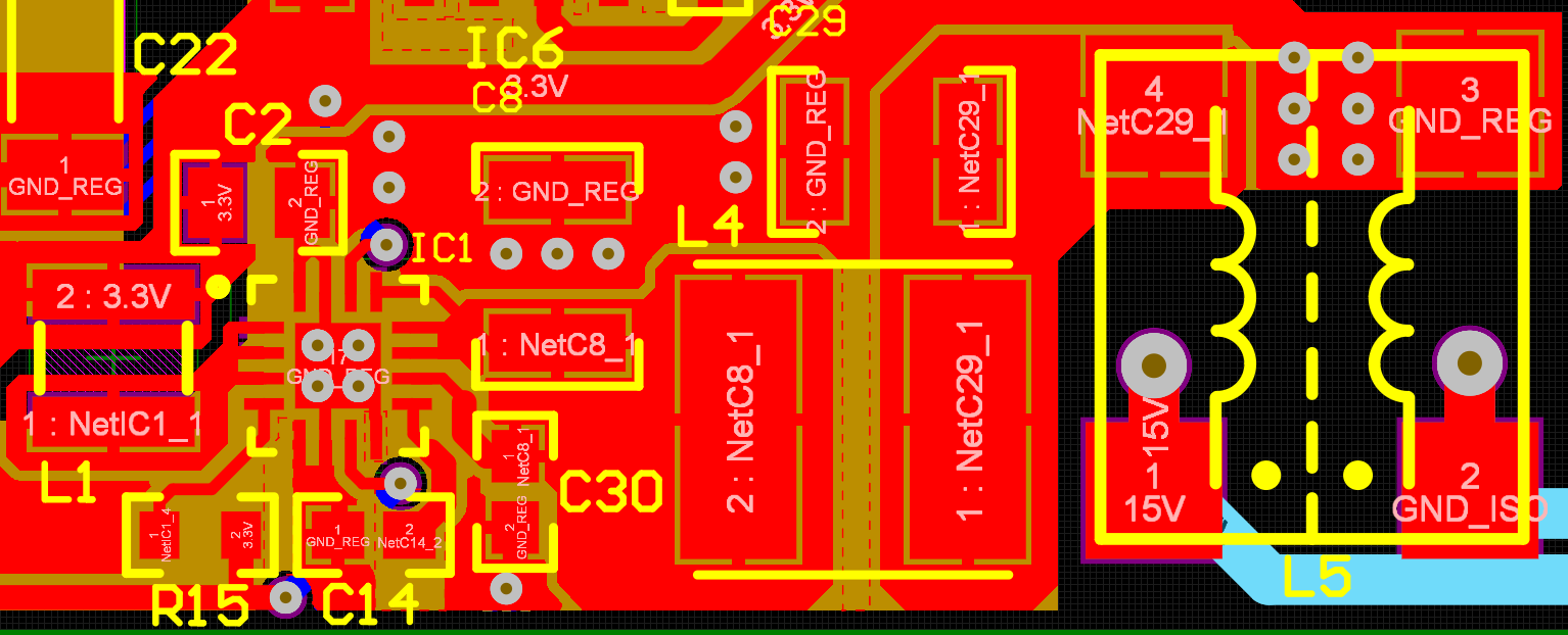
In the design process, I have paid close attention to datasheet suggestions regarding layout and surrounding components.
In the design process, I have paid close attention to datasheet suggestions regarding layout and surrounding components.
However, I have a problem: When I apply 15VDC to the input of the converter, I get 0VDC output (no output).
At this moment the converter (whithout a load but with all surrounding components in the schematic) pulls arround 36uA.
I have tried replacing nearly all components except for the input filter but have had no success. I have made measurements
to make sure all surrounding components do in fact make contact with the IC and that everything is connected as should be.
to make sure all surrounding components do in fact make contact with the IC and that everything is connected as should be.
At this point I am starting to think the problem is with a PCB manufacturing malfuntion and I am going to assemble a new pcb.
Can you confirm that the design is correct? I have included the schematics and the pcb design.
The IC is configured for 1.25MHz operation
I know this is a very broad question so let me know if I can supply any more details or made calculations.
Greetings,
Maarten