A related question is a question created from another question. When the related question is created, it will be automatically linked to the original question.
If you have a related question, please click the "Ask a related question" button in the top right corner. The newly created question will be automatically linked to this question.
Part Number: LM5021 Other Parts Discussed in Thread: PMP10215
Hi Team,
We want to use PMP10215 for our product, and we find a question about this circuit, pls. help to explain the function of the below circuit red highlight.
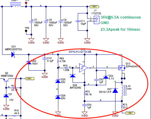
The circuit in the red line is actually a Buck converter.
When the voltage on C12 is higher than V(D25)+V(D28), which means we have a spike on anode of D31, we have a current through R69. If this current is sufficient to drive the Schmidt trigger input (pin 2 of SN74LVC….), then we have a Ton over Q13. During this small Ton (which is synchronous with switching waveform of the main converter, but has duty cycle dependent on the amount of energy is contained in the spike), the Buck converter, defined by Q13, L10 and D27, will inject the energy during Ton into Vout (36V).
This way the energy in the spike is recovered cycle-by-cycle and not wasted in a snubber resistor. It’s actually an “active snubber”.