This thread has been locked.

If you have a related question, please click the "Ask a related question" button in the top right corner. The newly created question will be automatically linked to this question.

LMZ14201: concern with EN pin driving by LM3880 still open

Part Number: LMZ14201
Other Parts Discussed in Thread: LM3880

Hello

Great to have close all the threads without to have wait a solution

so my situation is still NOT SOLVED

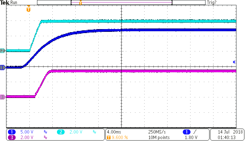
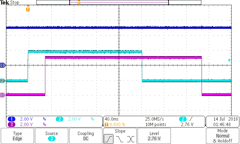
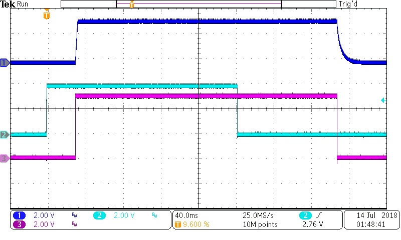
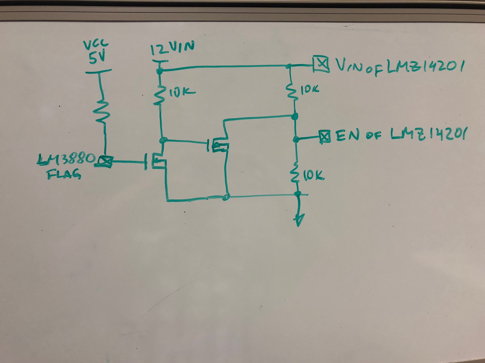
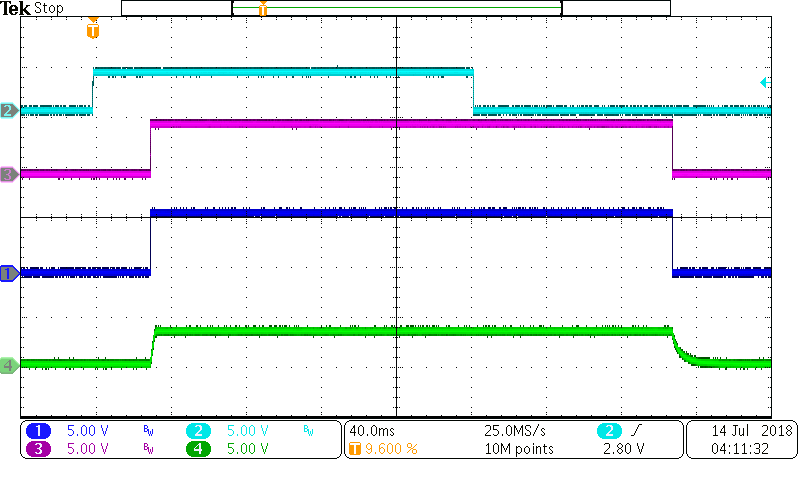
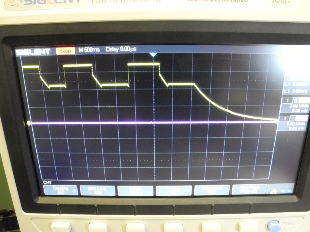
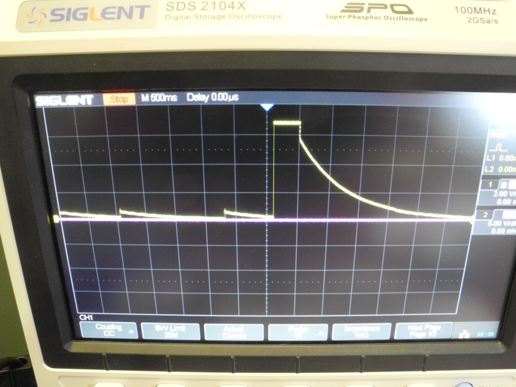
I have test with a buffer transistor ( NPN 4401 ) wit several resistor value as 20K 10K and 1K and now succeed to to not burn the LM3880 but I have strange sequence on the LMZ14201 both start and shut down power I link both schematic

Regards

David

  • Hello David,

    I am sorry that you are still having issues.


    Regarding closed threads – actually you can re-open any closed discussion by replying to the latest message with more information. This will re-open the conversation and we can continue on with all the background information available there. In my opinion, this is much better than submitting a new thread every time. I think you have started at least 3 threads on the same topic…If another engineer is trying to assist you, she/he may not have all of the relevant information if this is a brand new thread.

    Regarding the issue you are having – you posted a schematic above with a BJT and a resistor, but it is not clear how the LMZ14201 and the LM3880 are connected there. Can you please clarify how you are connecting the circuits? In terms of the waveforms, can you please clarify what is on each channel?


    Question: Did you try the n-ch FET suggestion we had in the other two threads you posted on this?

    https://e2e.ti.com/support/power_management/powermodules/f/501/t/706398

    I think it should solve your issue – please let us know if you tried it.


    Cheers,
    Denislav

  • Hello David, 

    I ordered LM3880 and LMZ14201 evaluation boards to test this out. I removed the resistor divider on the EN pin on the LMZ14201 board so that the EN pin is floating. 

    Here is the LMZ14201 evaluation board startup with the EN floating:

    CH1 = VIN (12V)

    CH2 = EN (floating), internally pulled up by a 6uA current source and internally clamped to 5V minus a diode drop. I have shared the internal clamp diagram before. As you can see, the voltage on the EN pin when left floating does not exceed 5V.

    CH3 = VOUT (3.3V) 

    --------------

    Here is now the LM3880 by itself:

    CH1 = VCC = 5V supply

    CH2 = external logic input from function generator

    CH3 = FLAG1 (pulled up to the 5V supply)

    So far so good. 

    Here are the two circuits working together - the LM3880 Flag 1 driving the EN pin of the LMZ14201:

    CH1 = The output voltage of the LMZ14201 (3.3V in this case)

    CH2 = input to the LM3880 sequencer from a function generator. 

    CH3 = FLAG1 (output of the LM3880) = EN pin of the LMZ14201 device. 

    I ran the two ICs together (LM3880 driving the LMZ14201 directly) for 90 minutes, with a 2Hz pulse without any issues. This is more than 10k cycles without a problem. Again, this is the LM3880 driving the LMZ14201 directly, without any additional circuitry for level shifting, etc.


    I am not sure why you would get a failure on your side with this configuration. The voltage on the EN pin is clearly not exceeding the 6.5V max. 

    Is it possible for you to capture waveforms on your scope to compare to what I see? Please monitor the following nodes:

    1. VCC of the LM3880 device

    2. VIN of the LMZ device

    3. The logic input to the LM3880 sequencer

    4. The flag output of the LM3880 sequencer driving the LMZ EN pin

    Regards, 

    Denislav

  • Hello David,

    For the sake of completeness, I also put together the circuit with the two n-ch FETs between the LM3880 and the LMZ14201. Here is a diagram of what I tested. You can adjust the resistor divider so that the EN voltage is not exceeded when the bottom FET is OFF.

    Here is a waveform:

    CH2= logic from a function generator driving the LM3880

    CH3=FLAG from LM3880

    CH1=EN pin of the LMZ14201 (output of the n-ch FET circuit above)

    CH4= output voltage of the LMZ14201

    Again, I don’t think you should need the external FET circuit, but this should help if you think the 5V on LM3880 is getting exceeded for some reason.

    Sincerely,

    Denislav

  • Hello David,

    Please let us know information above resolves your issue.

    Cheers,
    Denislav
  • Hello Denislav

    Sorry for my late answer but I have strong concern on my project

    I am in process to design a modified to incorporate your cascade Mosfet solution I will test in two weeks time to received the PCB from now I will post results

    on my posted oscilloscope screen print the yellow trace is the LM14201 output

    I have make also tests with a direct link ( straight track PCB ) between the LM3880 and the LMZ14201 , That also work but some time after random cycle the LM3880 burn , I have run this trial with several LM3880 both AB and AC type I have perfect function up to several cycle and after that burn the LM3880 randomly .

    I will keep you informed of the next experiments results

    Note : the RED TEXT in my previous post was not for you but for the TI forum manager as my mail box is flood by emails and reminder , I really appreciate your help and the help of the other members

    Regards

    David

  • Hello David,

    Sounds good. Please use this thread if you want to continue this conversation once you have more results. This will ensure continuity.

    Cheers,
    Denislav