Other Parts Discussed in Thread: CSD87312Q3E
Greetings! We are experiencing a fault condition on this charger that we are hoping you can help us resolve.
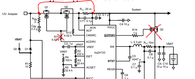
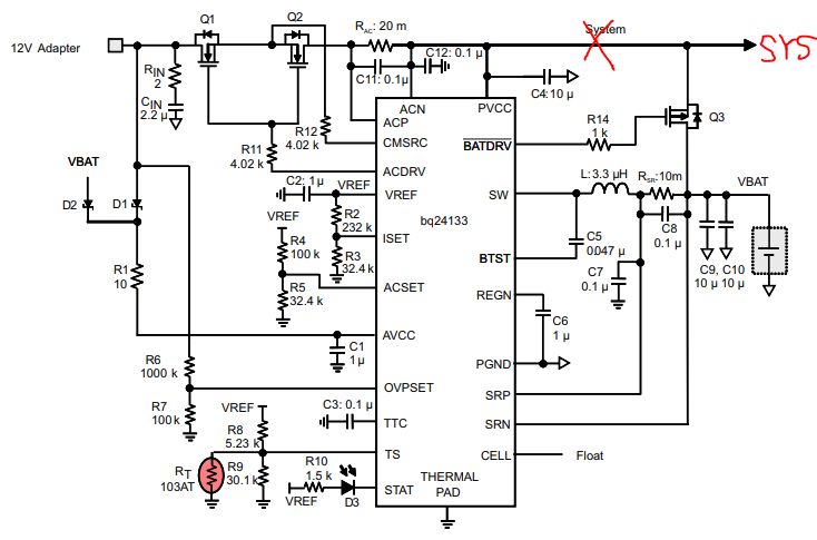
Our setup: we are using the BQ24133 charger chip with a 2 cell Lipo battery with capacity of either 6 Ah or 10 Ah. It has a built in 10 kOhm thermister. We laid out our schematic exactly as the example circuits in the datasheet. We used all the example circuit values. So our charge chip values should be: VIset= 403 mV (should result in 1.01 A charge current limit), VACSet = 0.82V to 1V (should result in 2.5 A input current limit). Our power supply is a 12 V AC adapter. We do have the STAT pin tied to one of our system microcontrollers as well as to the stat LED.
Our problem: we will have the 12 V adapter and the battery plugged in and charging (stat LED is solid red), then when we turn on the power to the load, the charger goes into fault (stat LED blinks). If we unplug the 12 V adapter and plug it back in, it usually clears the fault (sometimes it takes more than one unplug/plug attempt to clear the fault). The problem is almost exactly the behavior as defined in section 9.3.19 of the datasheet.
With our system fully booted, we are pulling minimum 2 A and up to 30 A into our load.
Things we’ve tried:
1. We verified all the conditions of section 9.3.9 in the datasheet for enabling the charging. They are all within the required limits before and after switching. We did not verify them during switching, but if they are stable after switching we feel like that should be sufficient to enable charge again.
2. Increasing the current limit on ACSet by replacing R4 (on the TI datasheet, nominal value 100K) with a new resistor valued 10.4K, leaving everything else as-is, so the new current limit should be 6.25 A. This didn’t solve our problem.
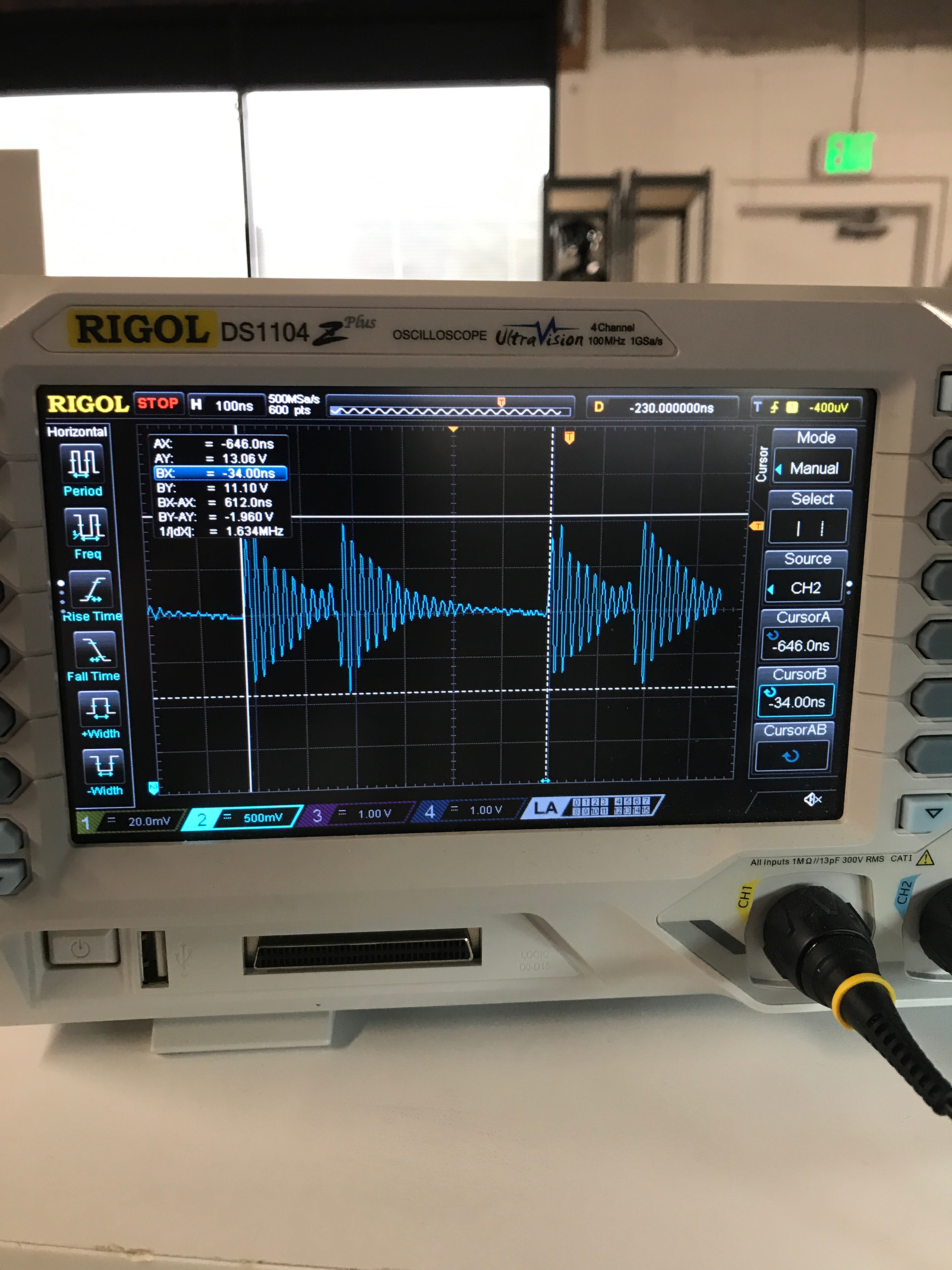
3. Thinking about section 9.3.19, we measured the voltage across both ACFET and BATFET. The waveforms that were obtained upon powering up the system are shown in the image below.
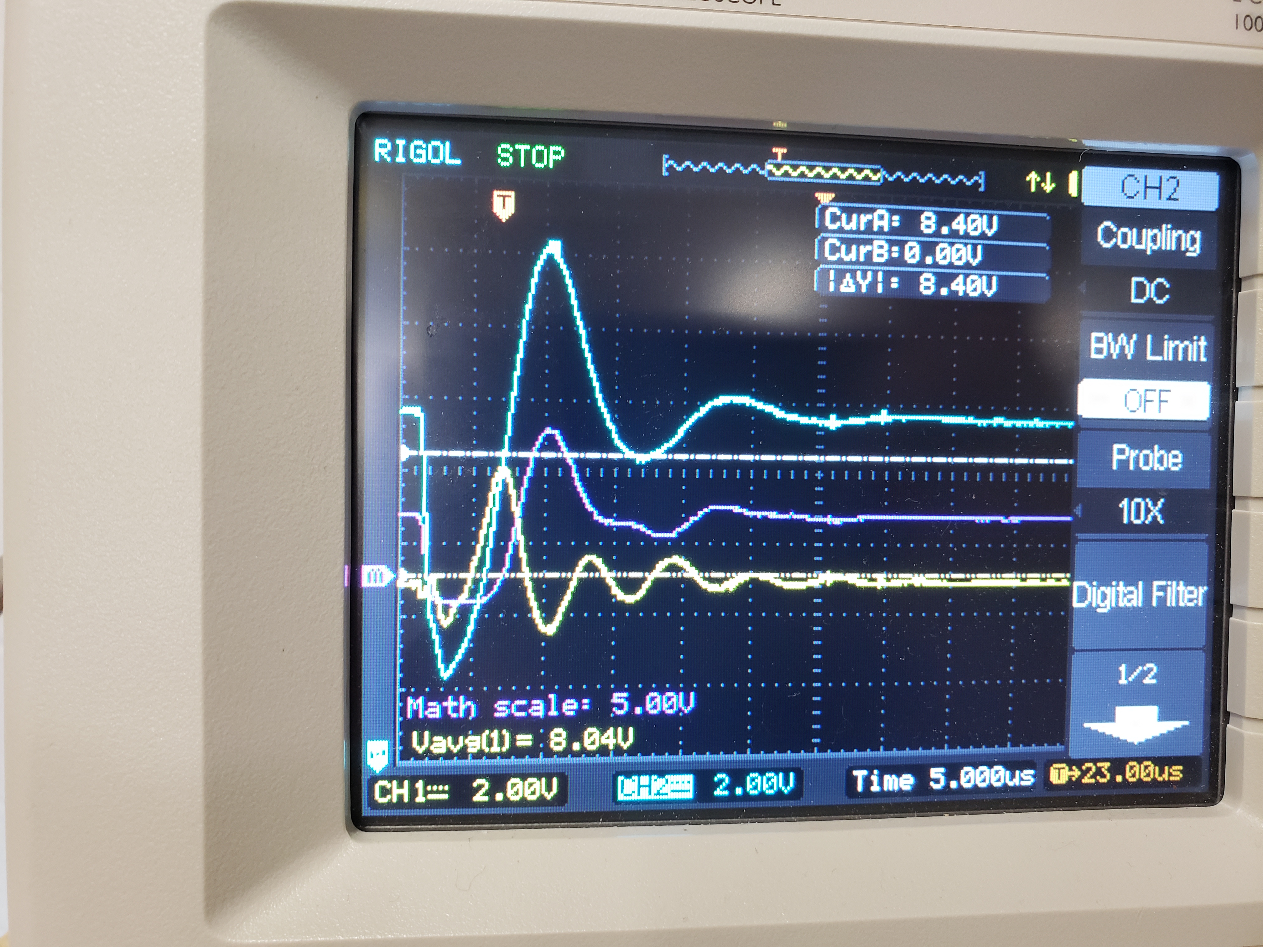
CH1 (yellow) is VBAT. CH2 (blue) is the 12 V adapter. Purple is the MATH channel doing a difference between them.
With such a large voltage sag, we suspected inrush current trying to charge capacitors. Going off the last line in section 9.3.10, we added capacitance between the Source and Gate of Q1, Q2, and Q3 to try to slow the inrush current, but after adding 114uF of capacitance, we were unable to prevent the fault. Then we tried slowing down the inrush by placing a 56 Ω, 1 W resistor in line with the AC power in, we were able to consistently run our system without the board going into fault (only running the system at 2 A).
We are looking for inrush protection circuits with the right level of inrush protection that also work at 30 A. However we want to verify that the problem isn't in the circuit of our BQ24133. We are on the fence about where the problem actually lies, so we are hoping to get some input from this forum.
Please ask any questions, and we'll try to answer them expeditiously! Thanks!