This thread has been locked.

If you have a related question, please click the "Ask a related question" button in the top right corner. The newly created question will be automatically linked to this question.

TLV700-Q1: Power Supply Rejection Ratio

Part Number: TLV700-Q1

Hello ,

I have looked on  TLV70033QDDC*Q1 datasheet very well but I could not find how to conclude the Power Supply Rejection Ration for an input voltage equal to 5.1V [Coming from a DCDC converter  with a switching frequency equal to 1.28MHz] , a 3.37V as output voltage.

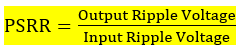
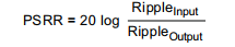
I need this PSRR value so that I can decide about the output ripple voltage as the    at all frequencies (  http://www.ti.com/lit/an/slva079/slva079.pdf ) .

So, could you please provide me with this value, or suggest me a method to calculate the Output Ripple Voltage using my functioning conditions.


Thank you so much,

  • i Ouissal,

    The picture you uploaded is not visible. Will you try to attach it by clicking the "Insert Code, Attach file and more..." text on the right bottom corner of the post editor window? Please see the screenshot I took to show you the place you should click to attach picture. 

    Regards, 
    Jason Song

  • Hello Jason,
    This the formula I found on the file mentioned above


    But after a while looking on the internet I found this second formula (http://www.ti.com/lit/an/slaa414a/slaa414a.pdf )


    So could you please precise to me which one to use and why?

    Thank you so much,

    Cordial Regards,

    Ouissal BOUDIR


  • Hi Ouissal,

    PSRR is defined as the ratio of the change in supply voltage to the equivalent (differential) output voltage it produces. In datasheet, the PSRR plot is expressed in decibels. Please use the PSRR = 20 log (Rippleinput/Rippleoutput) for your calculation.

    The application note you attached is a good example how to use the PSRR to estimate the ripple on the output caused by the injected ripple on the input. (www.ti.com/.../slaa414a.pdf)

    The datasheet has one PSRR plots that shows two load conditions when Vin - Vout = 0.5V. For your case, your application have a higher margin between the 5.1V vin and 3.37V vout and it tends to give you better number than the ones in the plot. You can see, at 1.27MHz, the PSRR reading is ~45dB - 53dB (based on the load). You can then use 45dB as a worst case estimate. In order to calculate the ripple on the output, you will also need to measure your input ripple at 1.27Mhz and then you can use PSRR = 20 log (Rippleinput(mV)/Rippleoutput(mV)) to estimate its effects on the output.

    Please let me know if you have any questions.

    Regards,
    Jason Song
  • Hello Jason,
    Thank you so much for your feedback, you asked my question as I needed.

    Cordial Regards,
    Ouissal