This thread has been locked.

If you have a related question, please click the "Ask a related question" button in the top right corner. The newly created question will be automatically linked to this question.

UCC28633: UCC2863x datasheet typical application question

Part Number: UCC28633

Hi,

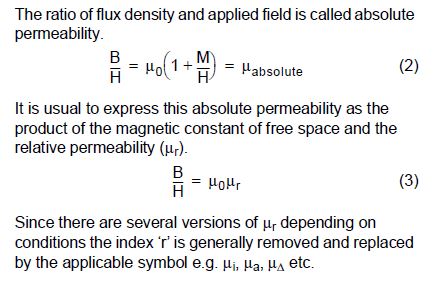
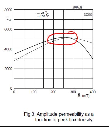
I am trying to understand the typical application example in the datasheet of UCC2863x. Under section "9.2.4.7 Transformer Selection and Design", I am having a difficult time to use the equation 46 in my application parameters. In the equation there is a "relative permeability" variable which is taken as 5500 for the selected core material 3C95. In the material specification document of that material, there is only initial permeability (3000) and amplitude permeability (5000) is given.

How did you obtain the value 5500 for relative permeability? Amplitude permeability is close but not the same. Or maybe we supposed to get the value from the graphs of the material with some parameters like temperature, max flux density etc.

Right now I am trying to select a core for my application which is made of CF139 material. The manufacturer only shares the initial permeability (2100) for that material.

This relative permeability of core materials subject comes across a bunch of times now and if someone explains it to me I would be grateful forever.

Thanks in advance.

  • Hello Emre,

    Thank you for your interest in using the UCC28633. 

    The following snippet from page 7 the Ferroxcube Soft Ferrites and Accessories Data Handbook 2013 indicates that the relative permeability value depends on the context of the calculation (page 8 of the pdf file).

    The author of the UCC2863x datasheet may have chosen 5500 for 3C95 based on this curve on page 94 (page 95 of the pdf) where the operating point of the transformer may increase the amplitude perm above the 5000 spec'd point (at 200mT, 25kHz, 100C).

    If you recalculate equation 46 using 5000 instead of 5500, it reduces the calculated gap by about 8um so there would seem to be some degree of precision needed, however, the air-gap fringing effect discussed in the next paragraph tends to muddy that water a bit. 
    For relative permeability, I recommend using the amplitude permeability from the material curve based on the expected operating conditions for your particular design.  More than likely, you (or your transformer vendor) will be adjusting the actual core gap dimension to obtain the inductance you need, after using the calculated gap as a starting point.

    Hopefully the CF139 material specs has a similar perm curve.

    I hope this answers your question.

    Regard,
    Ulrich


  • Hello Ulrich,

    Thanks for your effort in explaining how to approach my problem. What I understand is:

    - Relative permeability is really a relative term.

    - We could use the amplitude permeability vs. flux density graph to get a reasonable value. However, these graphs are formed in a certain frequency and our operation frequency could be different. We should also consider our operating temperature. In the end, we will derive a guess value from the graph with these details in mind .Then, we can use it to calculate the air gap.

    - Due to air gap fringing effect or some other reason this calculated air gap value needs to be adjusted experimentally to get the desired primary inductance after transformer winding is done.


    For my case, this is the graph:

    Unfortunately no test condition information has been shared. Nevertheless, correct me if I'm wrong: The author of UCC2863x takes Bmax as 315mT and he/she says that this is common practice. If I also do that, the intersection gives about the value 3750-4000 for the amplitude permeability. Lucky for me, 25C and 100C graphs behave similar at that region.

    I will take permeability as 4000 (I am trying to get the worst case scenario) instead of 3750, this will increase the calculated air gap. I will also make the iterations to take the fringing into account. This will increase the air gap, too. And then my transformer number of turns probably would not be enough to provide the desired primary inductance. Then I have to increase the number of turns accordingly.

    Am I on the right track here? What do you think?

  • Hello Emre,

    Sorry for my delayed reply; I was out of the office for several days.  

    The author uses 315 mT in the calculations based on an unstated premise.   It is not common practice to take Bmax as 315 mT, specifically.  In the datasheet, he says "For most power ferrites, a value in the region of 315 mT is commonly used."   315 mT is too specific of a target value to design to, since transformer design is an iterative process. What actually happened is that the author designed the example circuit ahead of time and arrived at a solution.  Using the resulting specific core, number of turns and other parameters of the final design, he calculated the actual Bmax and got the result of 315 mT.   He was then satisfied that this value of 315 mT was sufficiently low enough to not saturate under high temperature worst-case current conditions and also not be too low (indicating too many turns or too much core area) which would produce unnecessary losses or oversized transformer.  

    For the application space in which the UCC2863x is suited, most power ferrites have a high-temperature Bsat level somewhere at or above 350 mT.  Since the calculated 315 mT was reasonable enough, it was carried forward into the subsequent calculations.  It could have as easily been 303 mT or 347mT or such. 

    On the matter of air gap fringing, the fringe effect tends to increase the effective inductance greater than expected, so increasing the gap width to counteract that will only decrease the Lm down to what you want it to be.  You will not need to increase turns.  

    Be careful about widening the gap too much.  Excess fringing field will induce eddy current in the windings and cause serious local heating in the turns near the gap.  A lot of information can be found with a web search on "core fringing fields".  Another great source of general info on magnetics design is found at this link:

    I hope this helps you.

    Regards,
    Ulrich