This thread has been locked.

If you have a related question, please click the "Ask a related question" button in the top right corner. The newly created question will be automatically linked to this question.

TPS630250: Vout variable

Part Number: TPS630250

Hi everyone,

I implemented this circuit:


what be happening is:

Vin = 3.1 -> Vou = 1.3V

Vin = 3.6 -> Vou = 2.3V

Vin = 4V -> Vou = 2.8V

The circuit dont have load.

I tested with battery, and variable powersource.

I checked resistors and its correct value.

i have two boards and the problem is the same in both.

Someone have idea what can be happening?

BR

  • Hello Roberto,

    Would you please check the following:
    - voltage from the FB pin to the GND pin for different input voltages?
    - output voltage with oscilloscope
    - input voltage and output voltage with the GND reference connected to the GND pin of the IC.

    Best regards,
    Brigitte
  • Hi Brigitte,

    - voltage from the FB pin to the GND pin for different input voltages?

    The result is:

    Vin = 3.1 -> V FB = 0.178V

    Vin = 3.6 -> V FB = 0.527V

    Vin = 4V -> V FB = 0.672V

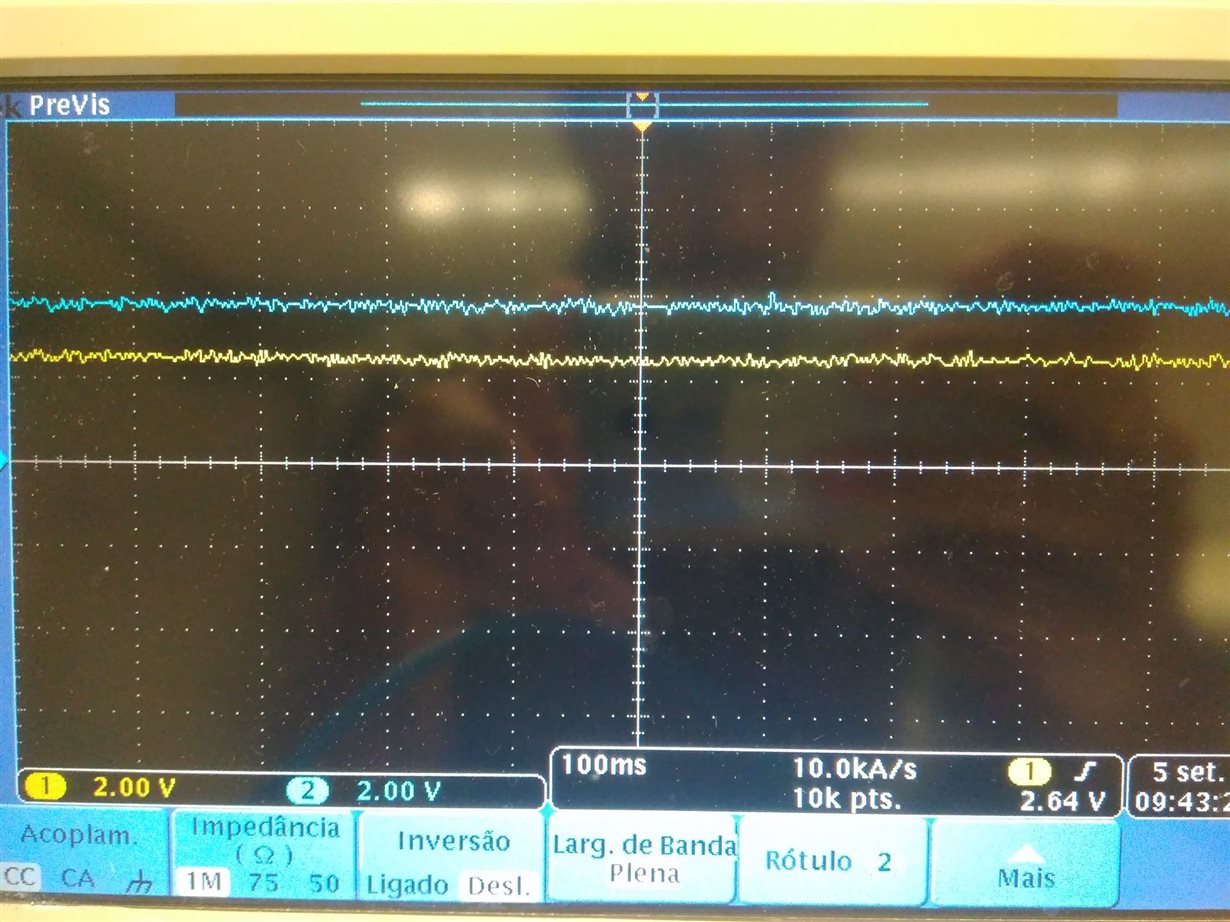
    input voltage and output voltage with the GND reference connected to the GND pin of the IC.

    Blue-  Vin

    Yellow - Vout

    thank you,

    BR

  • Hello Roberto,

    The feedback voltage has to be 0.8V.
    In your board, the feedback voltage is not even close to where it should be. Please check the switch nodes L1 and L2.
    If these are not switching, please check the output voltage, when you connect EN to GND.
    If you still observe voltage there after you discharge the output cap, the IC is most probable damaged. Please replace the IC and check again.

    Best regards,
    Brigitte
  • Hello,

    In point L1 and L2 i checked that is switching.
    Result:
    Vin = 3.1 -> V L1 = 0.116V and V L2 = 0.116V

    Vin = 3.6 -> V L1 = 0.029V and V L2 = 0.029V

    Vin = 4V -> V L1 = 0.034V and V L2 = 0.034V

    Do you know if is the expected?

    I will connect the EN to GND and check the Vout ( isnt easy in PCB :)) after i will share with you the result.

    thank you
  • Hello,

    I think that found my mistake, in my PCB the PIN 2 isnt connected to ground, its foating.

    only can be this.

    I will say the result to you when correct this

    thank you