This thread has been locked.

If you have a related question, please click the "Ask a related question" button in the top right corner. The newly created question will be automatically linked to this question.

TPS92314: Cout & RL selection

Part Number: TPS92314

Hello

Thank you for your support.

Please advise about Cout and RL selection

Q1 Please confirm

Cout is decided fomula (18) on TPS92314 data sheet.

Please confirm.

ESR of One LED is 2.7ohm? (a)

Or

ESR of 7 LEDs total is 2.7 ohm ( 0.38ohm for one LED)?  (b)

I saw following app note.

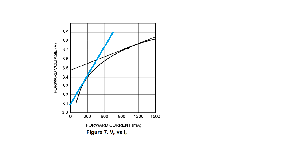
I' sorry that I don't understand the difference between ' dynamic resistance' in snva253a and

ESR in the data sheet. 

www.ti.com/.../snva253a.pdf

Customer will use ILED=350mA and 26 strings.

If (a) were correct, it should be ~1500uF but If xESR is very large.

Q2

If the Cout was decreased by Bias-voltage or temperature,what is the problem?( ripple will increased?)

So, calculation result of Eq (18) should be minimum Cout?

 Q3

How do we select RL(49.9Kohm) in the data sheet?

Best RegardsTPS92314_Cout.xlsx

  • Hello Kanji,

    Q1) ESR is a term I don't like to use with LEDS, dynamic resistance or impedance makes more sense. ESR is a term used for electrolytic, and other, capacitors which is equivalent series resistance. An LED's resistance changes depending on the current through it and operating temperature. If the dynamic resistance is 2.7 ohms, seven LEDs IN SERIES will be 18.9 ohms dynamic resistance. Equation 19 shows 7 * 2.6, this is just an example so it shouldn't matter in the customer's application since it will be different. IN PARALLEL the dynamic resistance will be 0.386 ohms but only if the current is seven times higher than the dynamic impedance of one LED calculation.

    Q2) If Cout is decreased current ripple will increase. On a PFC like this is will cause the 100Hz or 120Hz current ripple to increase not necessarily the switching frequency current ripple. If you are using maximum current ripple for the calculation then it would be the minimum Cout.

    Q3) RL appears to be just a load to discharge Cout when power is removed. At 21V (7 * 3V) the current through it will be 0.42 mA, power dissipation 8.8 mW.

    The paper you reference shows how dynamic impedance is calculated. It is the slope of the LED V-I curve at a specific operating point. Since the V-I curve is not linear the resistance changes when the operating current changes. The dynamic resistance will go down at higher current and up at lower currents.

    Regards,
  • Dear irwin-san

    Thank you for your answer.

    I want to know the original source of the value 2.6 ohm in data sheet .

    I'm sorry, the typical dynamic resistance ( described in snva253a ) seems to be 1.2~1.3ohm something..?

    (Please kindly see atatched )

    The original source of  2.6ohm in the data sheet is from any typical LED data sheet?

    Please let me know the part number which referes in the data sheet.

    Best Regards


  • Hello Kanji,

    Ohms Law is Resistance = Voltage/Current, this is the basis for calculating Rled.  The source for the number on the datasheet doesn't matter since it will be different for every LED and operating point.  There are several ways to calculate/measure Rled:

    1)  From you graph above operating at 1000 mA you can use ohms law to get a close approximation.  Rled = (V2 - V1)/(I2 - I1).  V2 and I2 are a point on the graph, for example pick 1200 mA, the voltage is about 3.77V.  V1 and I1 are another point on the graph, pick 900 mA, V1 is approximately 3.7V.  Rled = (3.77V - 3.7V)/(1200 mA - 900 mA) = 0.233 ohms.  If you look at the line at the extremes the Rled would be Rled = (3.85V - 3.47V)/(1500 mA - 0 mA) = 0.253 ohms.  This is close enough for design.

    2)  You can place all the datapoints in excel and use the equation generator to come up with an equation for the line and then calculate the slope at the desired operating point.  Take the derivative of the equation and enter the operating point is the most accurate.

    3)  You can use a lab supply and the LED used.  If operating at 1A, set the lab supply to 1100 mA and measure VF (at the LED).  Then set the lab supply to 900 mA and measure VF (again at the LED).  You have to make sure that the temperature does not affect the measurement.  If it is at a different temperature between the two measurements the calculation will be wrong since VF drops with temperature.  Use the same equation above Rled = (V2 - V1)/(I2 - I1).

    Note that this needs to be done for any led at the proper operating point.  The Rled for the above graph is approximately; Rled = (3.58V - 3.5V)/(600 mA - 450 mA) = 0.533 ohms.  It is not a fixed value, it changes with operating current and to some extent operating temperature.

    The graph above does not have a lot of resolution, normally I would pick the operating currents evenly to one side and the other, such as 1100 mA and 900 mA (+/- 100 mA) but it just calculating slope so it's close regardless.

    Regards,

  • Dear Irwin san
    Thank you for your support!