Because of the holidays, TI E2E™ design support forum responses will be delayed from Dec. 25 through Jan. 2. Thank you for your patience.

This thread has been locked.

If you have a related question, please click the "Ask a related question" button in the top right corner. The newly created question will be automatically linked to this question.

LM22679: Goes in current limit without any apparent reason

Part Number: LM22679

Dears, we are having troubles with the DC/DC step-down regulator. By time to time it stops to regulate correctly the output voltage and it looks like that is going in protection mode for overcurrent.

Here is the schematic:


When it is not properly working the output voltage (+15V) is 3.4 V the voltage on pin 6-IC84 is around 0.3 V and the pin 7-IC84 is almost 0.

I have try to reduced the R271 to 5.6kohm but this is not working.

Some times by replacing the component IC84 with a new one it start to work again, but not always.

Do you see any reason why the LM22679 can be damage by the following use?

Regards

Denis

  • I would try to disconnect the negative regulator from the output of the +15V and see if that helps.
    There may be some interaction. If possible, take some wave-forms of the switch pin and the inductor current
    during good and bad behavior.
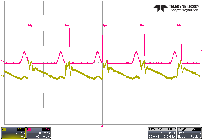
  •  1) When IC84 was not working and providing only 3.2 V at the output (+15V) and the IC85 was working providing -15V at the output, the Voltage on Pin 1-IC84 and current through the inductor was:

    C1: L12 current (100 mV = 180 mA)    C2: D52 voltage

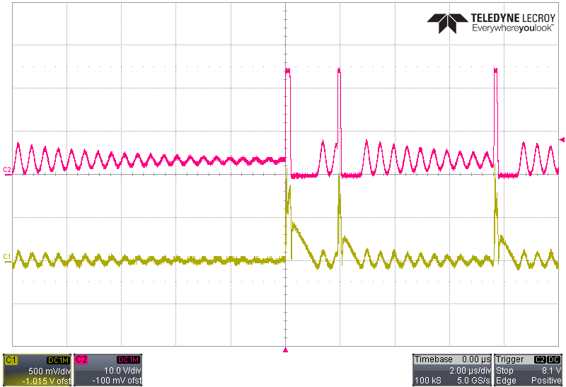
    2 ) I disconnect the IC85 (so the IC84 was only partially loaded by other components) and test as point 1:

    C1: L12 current (100 mV = 180 mA)    C2: D52 voltage


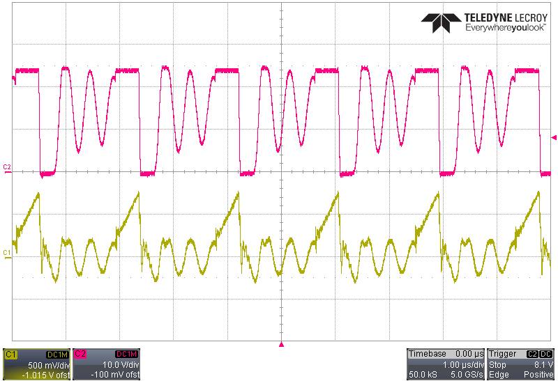
    3) I replace the IC84 with a new one and now the output is coreclty regulated at 15 V

    C1: L12 current (100 mV = 180 mA)    C2: D52 voltage

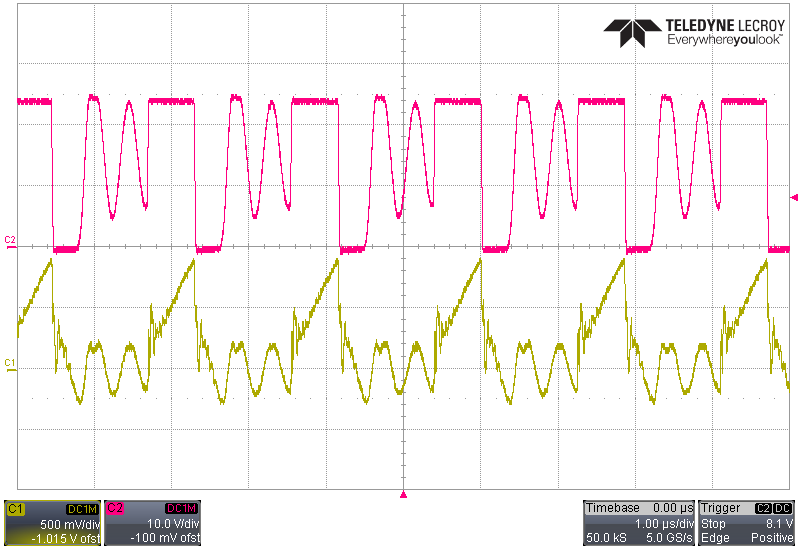
    4) I reconnect the IC85 and now all the outputs +/- 15V are working correctly

    In my opinion the IC84 was damage and it was not operating well. But this problems rise quite often, and I cannot understand the reason.

    Last time that I broke the IC84 I was just measuring the voltage with the oscilloscope probe connected to pin 6-IC84


    1) When IC84 was not working and providing only 3.2 V at the output (+15V) and the IC85 was working providing -15V at the output, the Voltage on Pin 1-IC84 and current through the inductor was:

    /resized-image/__size/1230x0/__key/communityserver-discussions-components-files/196/4555.par_2D00_icrosense6.png

    C1: L12 current (100 mV = 180 mA)    C2: D52 voltage

    2 ) I disconnect the IC85 (so the IC84 was only partially loaded by other components) and test as point 1:

    /resized-image/__size/1230x0/__key/communityserver-discussions-components-files/196/8360.par_2D00_icrosense7.png

    C1: L12 current (100 mV = 180 mA)    C2: D52 voltage


    3) I replace the IC84 with a new one and now the output is coreclty regulated at 15 V

    /resized-image/__size/1230x0/__key/communityserver-discussions-components-files/196/6177.par_2D00_icrosense9.png

    C1: L12 current (100 mV = 180 mA)    C2: D52 voltage

    4) I reconnect the IC85 and now all the outputs +/- 15V are working correctly

    /resized-image/__size/1230x0/__key/communityserver-discussions-components-files/196/4530.par_2D00_icrosense10.png

    In my opinion the IC84 was damage and it was not operating well. But this problems rise quite often, and I cannot understand the reason.

    Last time that I broke the IC84 I was just measuring the voltage with the oscilloscope probe connected to pin 6-IC84


  • The inductor current looks strange. Are you using a current probe ??

    It would be good if we could see your PCB layout
  • I sens the current by using a 0.56 ohm resistor in series with the inductor.

    Here is the PCB layout

  • You will need to remove all of the thermal reliefs on the power components and
    use solid connections. This includes the inductor, i/o caps and the diode and grounds.
    The smaller input caps, such as the 4.7u and the 100n need to be on the same side as the
    device and near the input pin. The diode ground also needs to be close to the input capacitor ground
    and the device ground. This is true for both regulators.
  • I soldered two SMD capacitors of 4.7 uF over pins 2 and 4, and make a strong connection between pin 4 and thermal pad. This seems to solve the problem.