This thread has been locked.

If you have a related question, please click the "Ask a related question" button in the top right corner. The newly created question will be automatically linked to this question.

LMZ20502: LMZ20502 1.2V output issue

Part Number: LMZ20502
Other Parts Discussed in Thread: TPS82084, ,

Dear Sir,

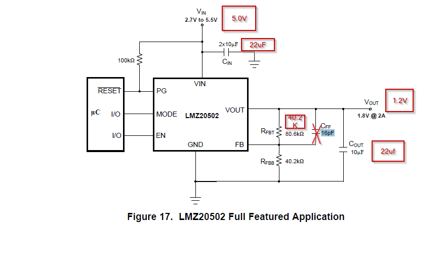
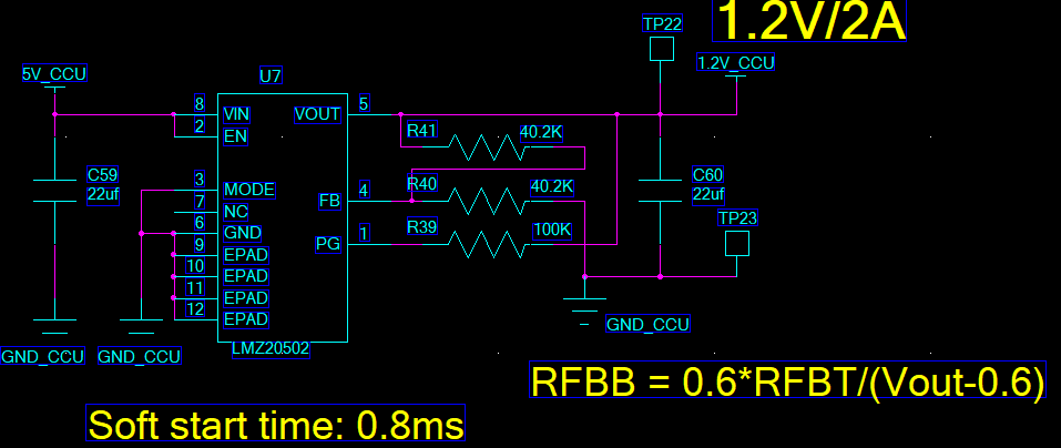
In fact I used TPS82084 in my previous design, it work well .because it cannot be bought in stock recently, I have to use LM20502 instead. but I forgot add Cff in my design.  the fig is just like this:

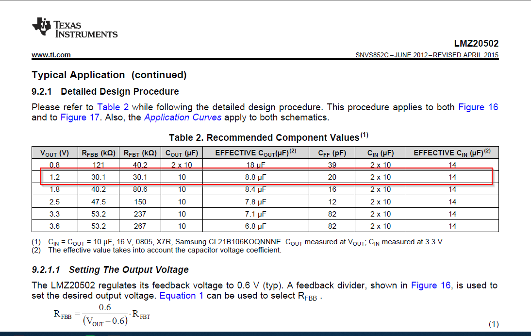
Vin is 5V, Cin and Cout is 22uf, both of Rfbt and Rfbb are 40.2K. Vout should be 1.2V  , but Cff is forgot to place.

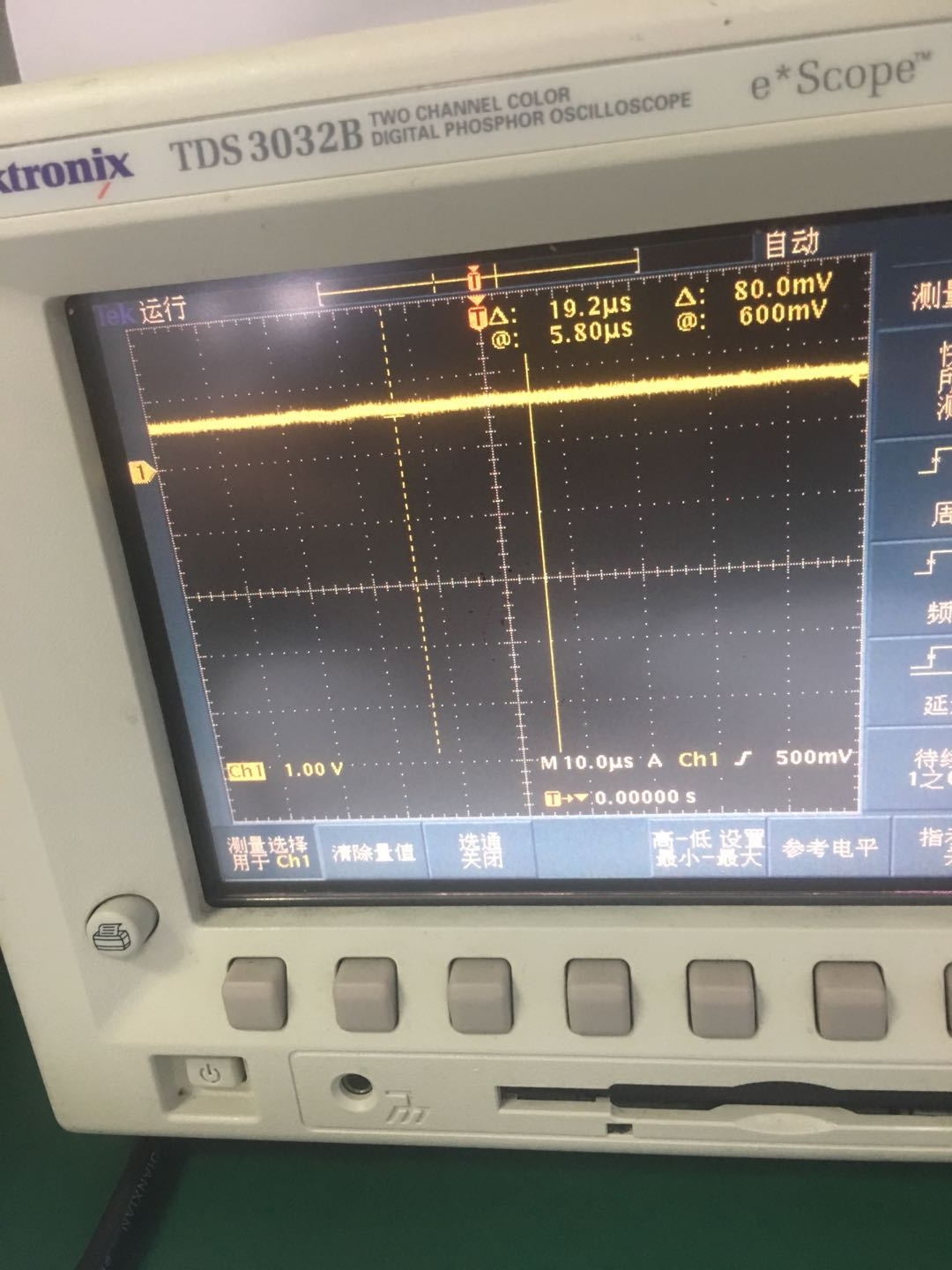
I measure the Vout,   about 0.89 V

So, I have some question:

1: Cff is necessary for this LMZ20502 usage? the real output is about 0.89V,   it is so smaller than 1.2V expected.  can this Cff impact on it?

2: Can 47pf cap be used ?  the suggested value is 20 pF。

3. Cout is 22uf, the suggested value is 10uF, can 22uF be used for Cout?

Best regards.


  • Hi David,

    Do you have any downstream capacitance connected to the 1.2V output of the LMZ20502? The maximum recommended effective output capacitance for this part is 100-200uF. Anything above this will affect the loop stability of the system. Is is your effective Cin at least 14uF? Also do you have this repeating issue on multiple boards?

    Cff simply helps improve loop phase margin. The typical application detailed in the datasheet for are examples of tested conditions. The best way to check if the system is stable is to run a bode plot analysis to validate your design of Cff= 47pF with Cout= 22uF. 

    Regards,

    Jimmy 

  • Dear Jimmy,

    In fact, I just use LMZ20502 in stead of TPS82084, all peripherals are not changed. TPS82084 work well in my previous design, but LMZ20502

    I know much more capacitors in 1.2V downstream will affect the stability, much more capacitor will decrease the phase margin. but the total capacitors is 22uF * 3 = 66uF , much lower 200uF.

    and also total Cin which are connected with +5V supply is about 22uF * 5 = 110uF, is much bigger than 14uF.

    I also read some application notes in TI website which discuss Cff usage. it seems the Cff is focus on startup time or slope time while power on.

    I will solder Cff with 16pF or 20pF and check it again.

    Best regards.
  •  Dear Jimmy,

    I had soldered Cff and check again, it seems no change, Vout is 0.84V  measured by Multi-meter. the digital oscilloscope capture attached. it show Vout is 0.6V and Vpp is about 80mV.

    Can you give me further suggestion?

    Thanks.

  • Dear Jimmy,

    This is part of LMZ20502 and for your reference.

    Thanks

  • Dear Jimmy,

    Another two LMZ20502 are also used in other pcb boards,  but them  are designed to generate 1.8V,  I had checked them, both of them are working well and also without Cff .

    It is crazy why LMZ20502 can not generate 1.2V.

    Thanks.

  • Hi David,

    Let me take a LMZ20502EVM and configure for Vin = 5V Vout = 1.2V with you BOM selection

    • Cin = 110uF 
    • Cout = 22uF
    • Rfbt = Rfbb = 40.2kOhm

    This way I can test on a known good unit and see if any issue occurs.

    Regards,

    Jimmy

  • Dear Jimmy,

    Wrong resistor is soldered, I replace it and LMZ20502 works well,

    Thanks.

  • Hi David,

    Thank you for the update. I was going to reply back yesterday that I didn't see anything funky on my test setup. Good to know the device is operating as it should.

    If anything else comes up, please feel free to continue replying to this thread. 

    Regards,

    Jimmy