This thread has been locked.

If you have a related question, please click the "Ask a related question" button in the top right corner. The newly created question will be automatically linked to this question.

UCC27423-Q1: UCC27423-Q1 rising and falling time

Part Number: UCC27423-Q1

Hi support team,

Questions concerning the UCC27423-Q1 datasheet(SGLS274H).

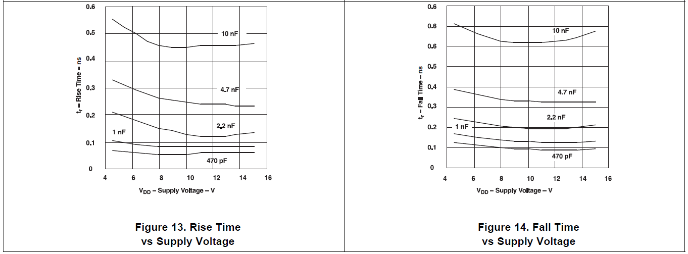
Values are different in "7.6 Switching Characteristics", "Figure 13", "Figure 14", but are figures correct?

For example, in Figures 13 and 14, Tr = 0.13ns and Tf = 0.21ns with VDD = 14V and Cload = 2.2nF.
Is the vertical axis of the figure incorrect?
Is Tr and Tf opposite to each other?
(For Tr> tf in 7.6, Tr <Tf in the figure)

Thank you.

  • Hi User,

    Thanks for pointing this error from our part.

    You are correct that the data (y-axis) and units from figure 13 and 14 seems to be incorrect.
    The figures in 7.6 table seems correct.

    Please allow me couple of days to investigate the y-axis scaling of the figures.
    I will then initiate a datasheet revision to update the document.

    Thanks for your patience.

    Regards,

    -Mamadou
  • Hi Mamadou

    Thank you.
    Waiting for your answer.

  • Hi User,

    Thanks for your patience.

    I can confirm that the y-axis values and units from figure 13 and figure 14 are not correct.

    Please only consider the values in the EC table while we engage datasheet revision which could take anywhere between 2.5 to 3weeks depending before the revised document is up and running.

    However, variations across supply range or cap load for rise and fall times are not significant.

    Additionally, consider the values on Table 7 from the EVM user's guide (copied below) for rise and fall times at 5V with 1.8nF cap load.

    www.ti.com/.../slvub27a.pdf

    Please let us know if you require further assistance or press the green button if this helped address your concern.

    Thanks.

    Regards, 

    -Mamadou

  • Hi Mamadou

    Thank you.

    In order to calculate the rise time in the actual design circuit,
    We estimate output resistance with respect to Cload from "Figures 13, 14".

    Please revise as soon as possible.
  • Hi User,

    Thanks for your patience.

    I am still working on your request.

    I am going to close this thread in the meantime and send you a friend request where I will share my email address in order to continue our communication there since the request will take weeks to resolve.

    Please feel free to post on a new thread if you need assistance with our gate drivers.

    Thanks.

    Regards,

    -Mamadou