This thread has been locked.

If you have a related question, please click the "Ask a related question" button in the top right corner. The newly created question will be automatically linked to this question.

CSD87350Q5D: TPS51631 and CSD87350Q5D with snubber circuit

Part Number: CSD87350Q5D
Other Parts Discussed in Thread: TPS51631

Hi,

I have been using the TPS51631 (Three phase power regulator) and CSD87350Q5D (MOSFET) to generate the CPU core supply for Intel Haswell CPU.

The design has been working fine if i do not add the snubber circuit.

If I add the snubber circuit to CSD87350Q5D (1R -resistor and 1nF - Capacitor), then CPU core rail is shorted and CPU is damaged.

I have used the snubber circuit values as specified in the datasheet.

Could you please suggest the reason that can cause the CPU rail to short with snubber circuit?

TI_Power_Supply_Design.pdfTI_Power_Supply_Design.pdf

  • Hello Boby,
    Thank you for your question. The R-C snubber circuit is used to reduce ringing at the switch node for each phase. It may or may not be required depending on the magnitude and frequency of the ringing observed at the switch node. I have a few questions and comments as detailed below

    1. How does the switch node ringing look without the snubber? Is it within acceptable limits?
    2. When measuring the switch node waveforms, make sure to minimize the GND connection on the scope probe to avoid picking up unwanted noise that may make the measurement look worse than it actually is.
    3. Typically, a shorted output can be due to a failed low side FET or a shorted component such as an output capacitor. In order to determine which, lift the output inductor on one phase at a time to isolate the power block from the output and check for shorts on either side of the inductor.
    4. Here are a couple of links on reducing ringing in buck converters:
    www.ti.com/.../slyt465.pdf
    www.ti.com/.../slpa010.pdf

    Please let me know what you find and I will be happy to help you resolve this problem
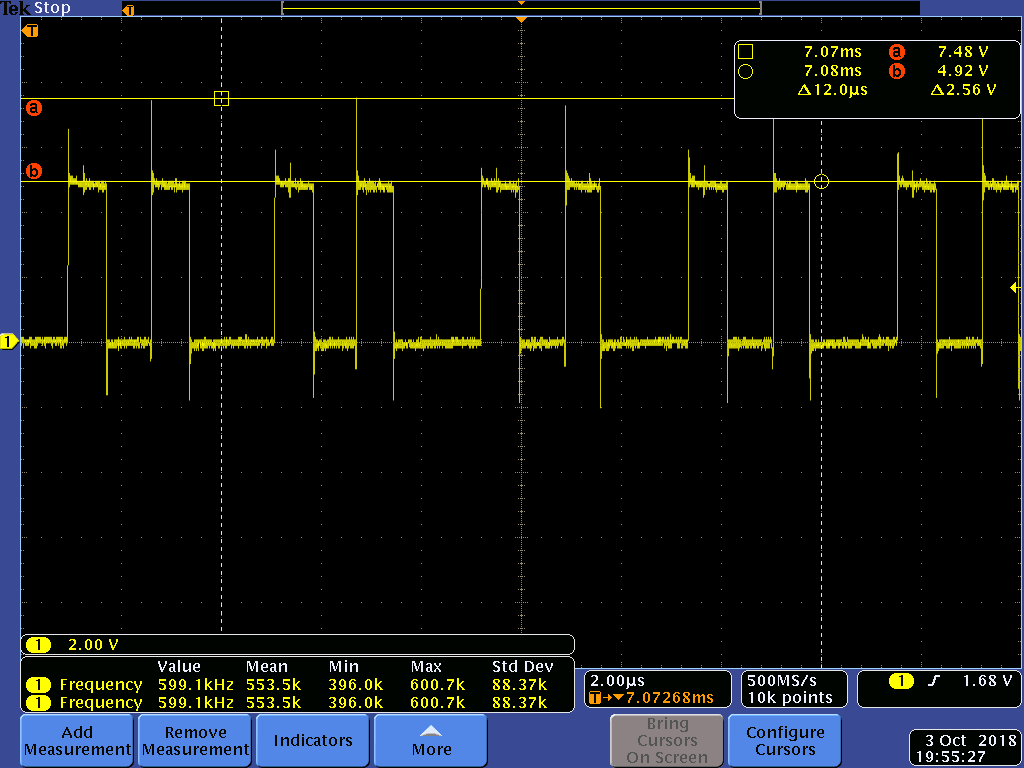
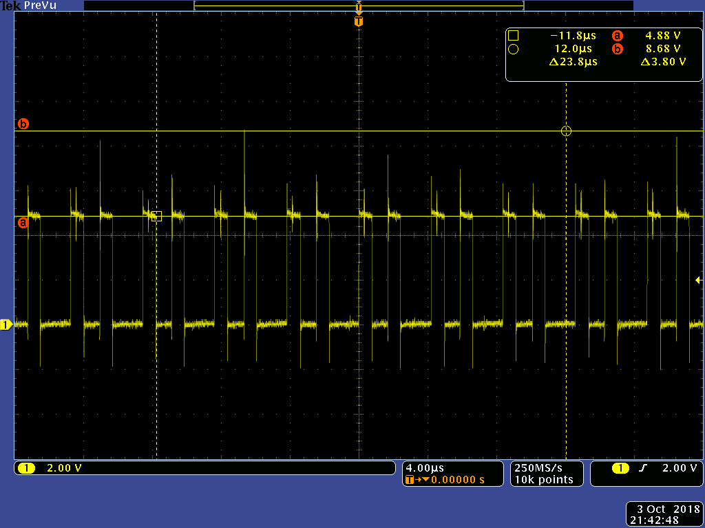
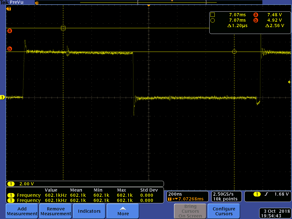
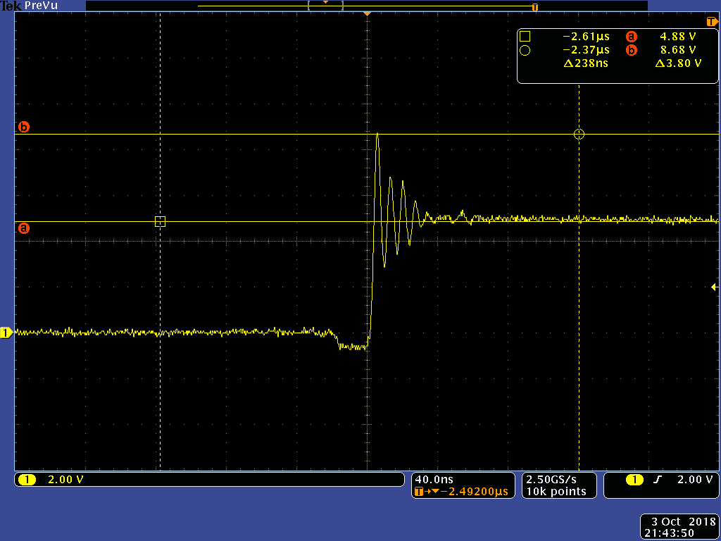
  • I have checked the noise at Mosfet output (at snubber circuit before inductor).

    With snubber circuit, the overshoot is reduced from 3.8V to 2.5V and ringing on overshoot is reduced.

    and the short occurs after the inductor.
  • Hi Boby,
    Thank you for capturing the waveforms. I didn't realize that the input to the converter is 5V. The FETs used in the CSD87350Q5D are rated at 30V max. The waveforms show that the peak voltage << than the 30V BVDSS for the device. In this case, the snubber is not required. However, if there are noise/EMI concerns then the snubber may help. The output being shorted after the inductor would seem to indicate that one or more of the output bulk capacitors have failed short. This usually occurs as a result of being exposed to an overvoltage condition in excess of the voltage rating of the caps. This would not be caused by the snubber circuit unless there might be a manufacturing defect such as a solder short. I would also recommend checking the high side FETs to see if any of them are shorted. This would cause the input to be directly connected to the output thru the inductor. You can check for a diode drop from the switch node to Vin to determine if the high side FET is shorted. If the body diode is OK, then the FET is not shorted.