


Other Parts Discussed in Thread: BQ500511A,
I'm currently using the BQ50002A and BQ500511A in a Qi transmitter design.
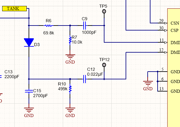
In the datasheet, there is a "Demodulator input signal conditioning" circuit.
This circuit takes the "TANK" signal and feeds pins 11 (DMIN 1) and 12 (DMIN 2). See below, from the datasheet:
I cannot find any documentation that specifies either the operation or the design choices behind these components.
Is the intention that we just copy this circuit directly from the application design?
Could someone please explain how this circuit operates, or the reason for component choices?
Kind regards,
Robert
