This thread has been locked.

If you have a related question, please click the "Ask a related question" button in the top right corner. The newly created question will be automatically linked to this question.

LMR14203: depending on the Cap IN, the buck converter burns

Part Number: LMR14203
Other Parts Discussed in Thread: LM2841

Hello!

I designed a project that uses the LMR14203 converter. After mounting only the power supply components I noticed that, sometimes, after powering up the circuit, the output is short-circuited.

I noticed that the LMR14203 was the component that was short-circuited. After several testings, in some cases the LMR14203 stops working, aparently nothing happened, but in some cases, the LMR14203 burned (please see attached video).

I also attached the schematic e layout designs. After doing some tests, changing the input capacitor for a tantalum type (originally I was using a X5R dieletric ceramic capacitor as recommended in the datasheet), the problem didn't happen anymore. I was using a swithed power supply: 24V-5A. What could it be if I was using the components selected by the Webench tool?

LMR14203 design.docx

  • Hello,

    How are you turning on the device? Are you plugging in the power cable? Is it possible there is any ringing at the input? If the part is okay with the tantalum capacitor, it seems the ESR resistance is dampening out the ringing.

    Could you try starting up the device to a lower input voltage with the ceramic capacitor (original capacitor) and probe the input voltage pin with an oscilloscope to see if there is any ringing at the pin?

    Best Regards,
    Katelyn
  • Dear Katelyn,

    Since I'm testing this new project, I'm powering up using wires to the switched power supply. I noticed that, in some cases, after connecting the positive wire (the negative I kept connected at all times, so I switch only the positive wire), the conversor stopped working. After that, I tested connecting and disconnecting the positive wire several times, in order to see if the IC stopped working. In those testings, the IC burned.

    The power supply is always on, what I switch off is only the power supply for my board. Since the power supply is switched type, and with short-circuit protection, I thought that there would be no noise. In my application the board will be supplied directly from a 24V vehicle battery (in a previous circuit there is a varistor and polyswitch for protection, and also a mosfet).

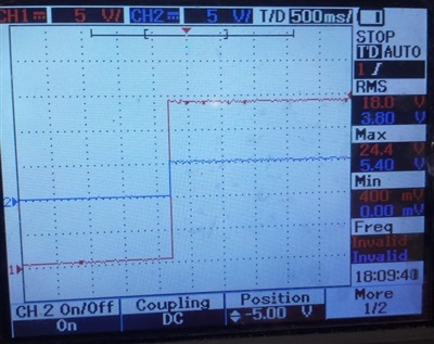
    I plugged the scope, measuring the input (directly in the input capacitor) and the output (output capacitor). I didn't see ringing in the input. This image shows a test where rhe converter is working (regulated to 5V):

    CH1 - input

    CH2 - output

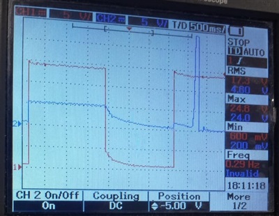
    And in this next image the converter burned as shown in the video:

    Regarding the capacitor change, it's strange that the ESR from the tantalum is 6.5Ohms, and the original (ceramic) says it's low ESR and ESL (datasheet).

    Thanks and best regards!

  • Hello,

    Thank you for sharing this additional information, and thank you for taking the lab measurements.

    Can you zoom in on the rising edge of the input voltage? We want to zoom in to see a few ms per division. Also, what is the bandwidth of the oscilloscope? We want to make sure that we will see the ringing. I would recommend at least 2MHz bandwidth.

    My suspicion is still ringing at the input. When you hot plug at 24V, it is very common to see ringing above 42V. Capacitors with ESR will dampen out some of this ringing. However, the best practice is to use protection circuitry at the input (TVS) to protect the downstream devices.

    For the datasheet recommendation, typically you want to use low ESR/ESL ceramic capacitors at the input for the best noise rejection and smallest parasitic loop (high DI/DT loop at the input of buck converter). This will help reduce high frequency noise at the switch node and output.

    Best Regards,
    Katelyn
  • Hi Katelyn!

    Thanks for your reply!

    I think today I'll be able to do some more testings with this converter. Regarding the input signal zoom, I can zoom in a little more, but I can't reduce the voltage scale because the offset is in the maximum  value. If I put in 2V scale (currently in 5V), the signal can't be seen. But regarding the ringing, the input needs to go higher than 42V, correct? In the measure done, the maximum value didn't reach 25V. The osciloscope I'm using is 40MHz.

    Talking about the input capacitor again, I tested almost the same circuit that I have in another PCB, but using the LM2841 regulator: using the ceramic capacitor that presented the problem in the first PCB, the converter burns as well. But using the tantalum capacitor with the 6.5Ohm ESR, the problem does not happen. I think it's strange because using the LOW ESR ceramic capacitor the problem happens, when in fact it should be better (thinking that the problem is related to the input voltage). If the problem persists, do you recommend to use this tantalum capacitor?

    Thanks and best regards! 

  • Hi,

    Yes, you are correct that it would have to ring at 42V. I would recommend using a diode for protection if the problem persists. You can use the diode to clamp in the input voltage. The ceramic input capacitor is better for decoupling and limiting high frequency noise. However, tantalum capacitor helps dampen out ringing due to the inductance of your cabling or PCB traces.

    Best Regards,
    Katelyn
  • Hello,

    I want to follow up on your post. Do you have any additional questions?

    Best Regards,
    Katelyn
  • Hi Katelyn!

    I wasn't able to test this project yet, but at first, we're using a tantalum capacitor in the input position.

    Do you think if I'd use a simple switch to turn the PCB on and off this converter burn wouldn't happen? Otherwise I think it would be safier to use the tantalum capacitor.

    Thanks and best regards!

  • Hello,

    The best option is to use a transient suppressor or a tantalum. You can use a tantalum with the ceramic. This will help dampen the ringing.

    Best Regards,
    Katelyn
  • Hi Katelyn,

    I'll trey to run more tests here, but since using only the tantalum capacitor, the problem was solved.
    Is it better to use only a tantalum capacitor, or a tantalum with a ceramic capacitor?
  • Hi Renato,

    Ideally you would use both. The ceramic capacitor would be placed closest to the device, and the tantalum closest to the input supply.

    The ceramic is meant to have a low parasitic loop from CIN, high side FET, and low side FET. The tantalum is being used to dampen the ringing from the power supply.

    Best Regards,
    Katelyn
  • Hi Renato,

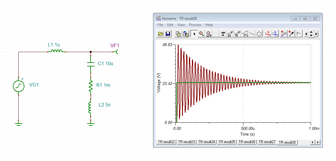
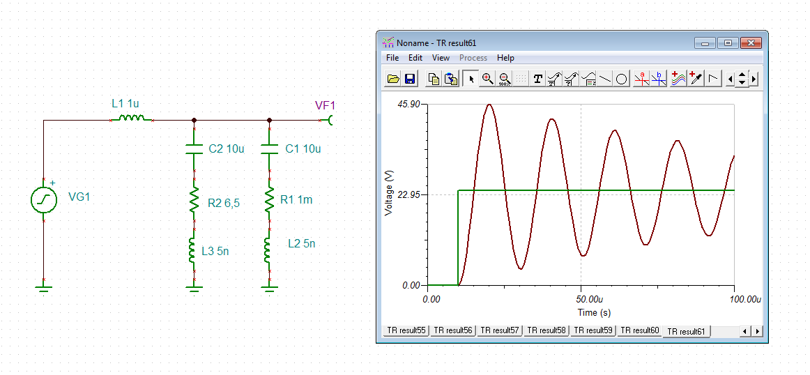
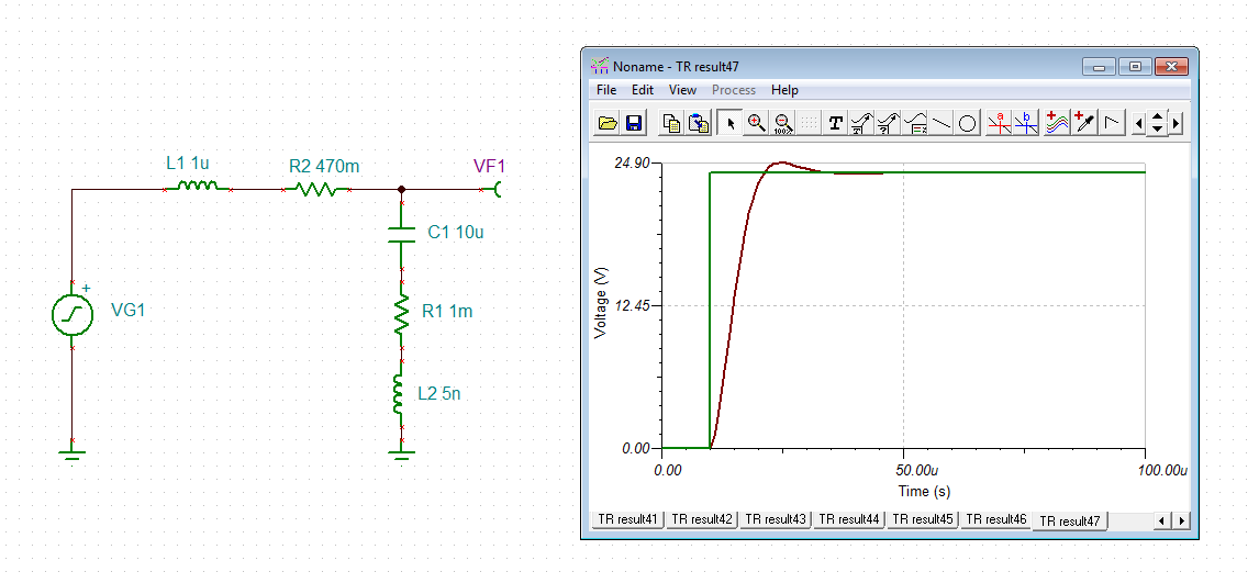
    I agree with Katelyn. Ceramic caps with their ultra low ESR can cause extreme ringing in combination with cabling. Here a simulation is shown with a 10µ/X7R with an ESR of 1mR. The input signal is a 24V step:

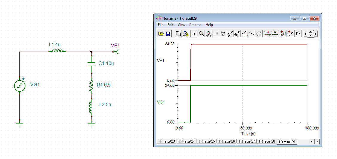
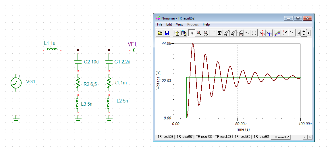
    And here with a 10µ tantal with an ESR of 6R5:

    Here the ESR of tantal very effectively dampens the series resonance of L and input capacitance.

    If the use of a ceramic input cap is desired, one remedy is to place a snubber in parallel to the ceramic input cap (Cin). A snubber is a series circuit made of a capacitance and a resistance. The capacitance should be made about 4 times the input capacitance Cin and the resistance should be chosen according to the formula

    R = 0.5 x SQRT(L / Cin)

    where L is the inductance of the cabling.

    But the snubber method only works, if the snubber is exactly matched to L and Cin. And even then you might nevertheless see a considerable overshot:

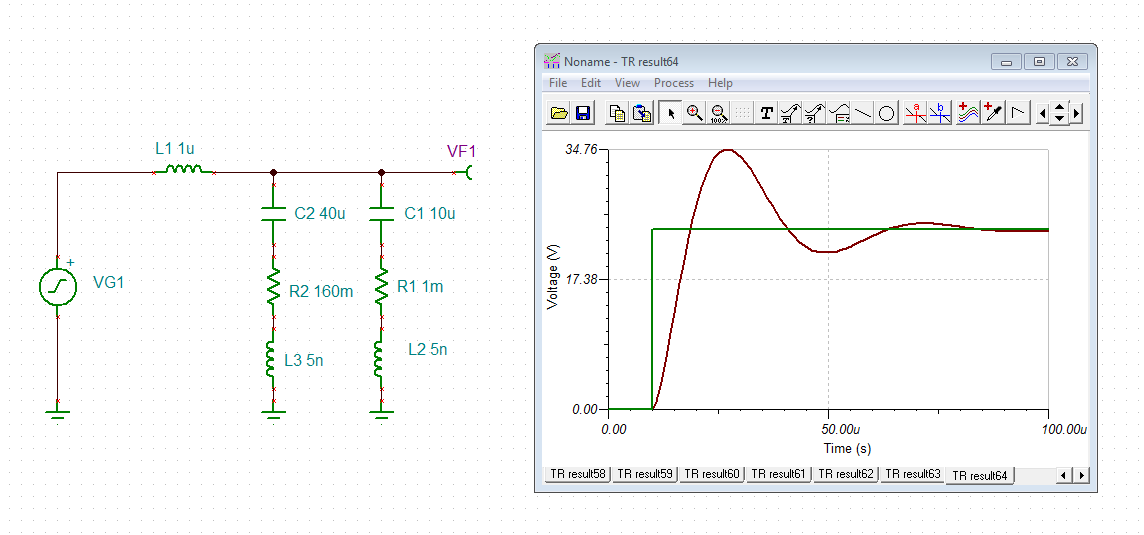
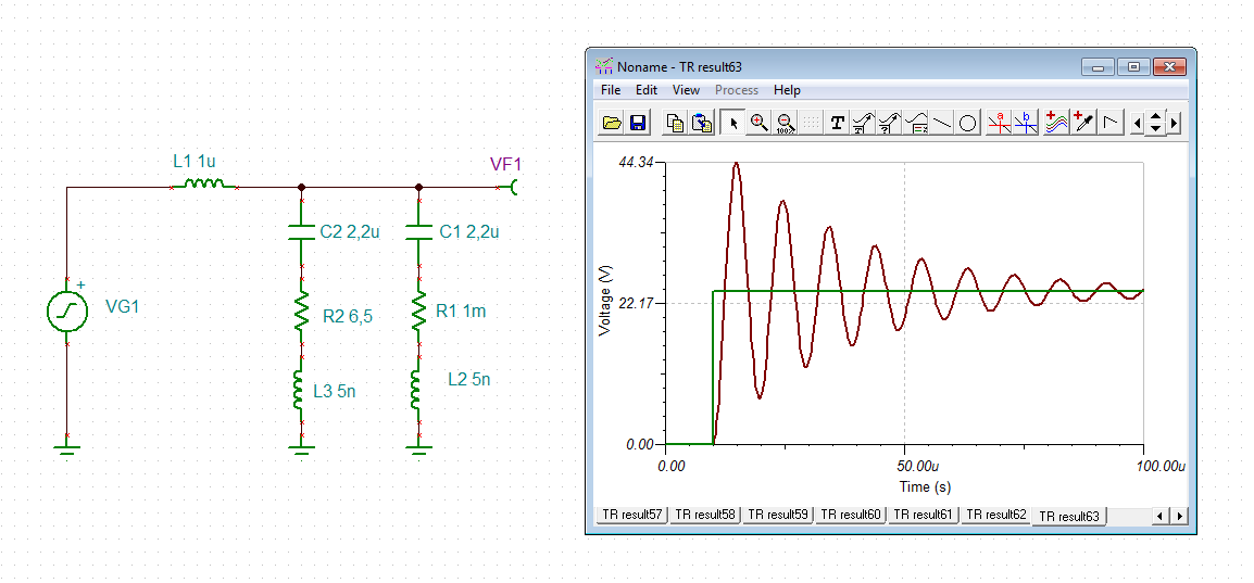
    Taking an arbitrary tantal in parallel to the ceramic cap might not help at all:

    Or this combination:

    Or this:

    A very simple but effective method is to put a little resistance in series to the input cap, according to the formula

    R >= SQRT(2 x L / Cin)

    renato.TSC

    Or, you could add a TVS to the ceramic cap, as Katelyn already mentioned. A tantal at the input should be avoided, though, because some variants don't like inrush currents.

    Kai

  • Hi Kai!

    Thanks for you reply!

    This was very helpfull! Is it hard to see this ringing using a scope? I tried to see it but I couldn't indentify this ringing with a scope we have here. It's a 40MHz scope.

    I have one question regarding the tantalum capacitor: why a high ESR damps he ringing?

  • Hi Renato,

    for better demonstration of the ringing I have omitted your diode D3 in the simulation. Remove it from your circuit and you will see the ringing. According to Mr. Thomson

    f = 1 / 2 / pi / SQRT(L x Cin)

    the ringing will occur at a frequency of about 50kHz, assuming L = 1µH and Cin = 10µF. So, it can easily be observed, even with a standard scope. (1µH is what is to expected with an input cable of 1m total length, according to the rule of thumb: 1nH/mm.)

    A high ESR is damping the ringing, because the energy stored in the electric field of Cin or stored in the magnetic field of L is "destroyed" into heat during every period of ringing. Every time the oscillating current is running through the ESR of L or Cin a bit of the stored energy is transferred into heat and leaves the circuit. It's like sitting on a swing and breaking with the feet... :-)

    Kai
  • Hello Renato and Kai,

    I am happy to see your continued discussion about ESR!

    The E2E threads lock and close after 1 month. Please start a new thread and we can continue the discussion.

    Best Regards,
    Katelyn
  • Hi Kai,


    Thanks!
    Dou you have any suggestion of materials regarding this issue?
  • Hi Renato,

    My recommendation would be to use a low ESR materials for your input capacitor for your parasitic loop with a medium ESR material (tantalum) for your input capacitor to dampen the ringing. You could also consider looking at electrolytic capacitors for dampening.

    Best Regards,
    Katelyn