This thread has been locked.

If you have a related question, please click the "Ask a related question" button in the top right corner. The newly created question will be automatically linked to this question.

TPS22922: Device Failures

Part Number: TPS22922

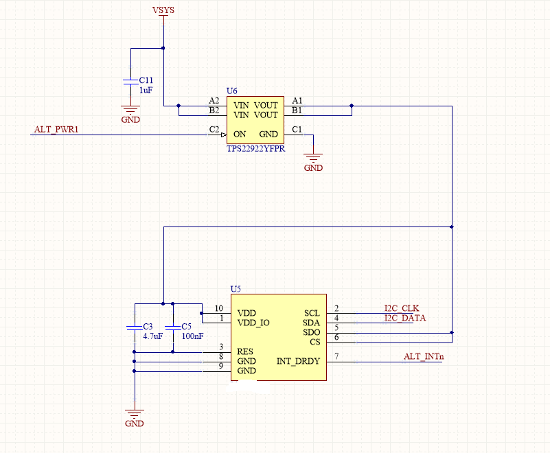
I am currently using the TPS22922 load switch in a very simple application where it controls the power to a small altimeter. The input voltage to the load switch is between 2-3V (Coin cell). Input capacitance is >> than the output capacitance. The on signal is controlled by a micro.

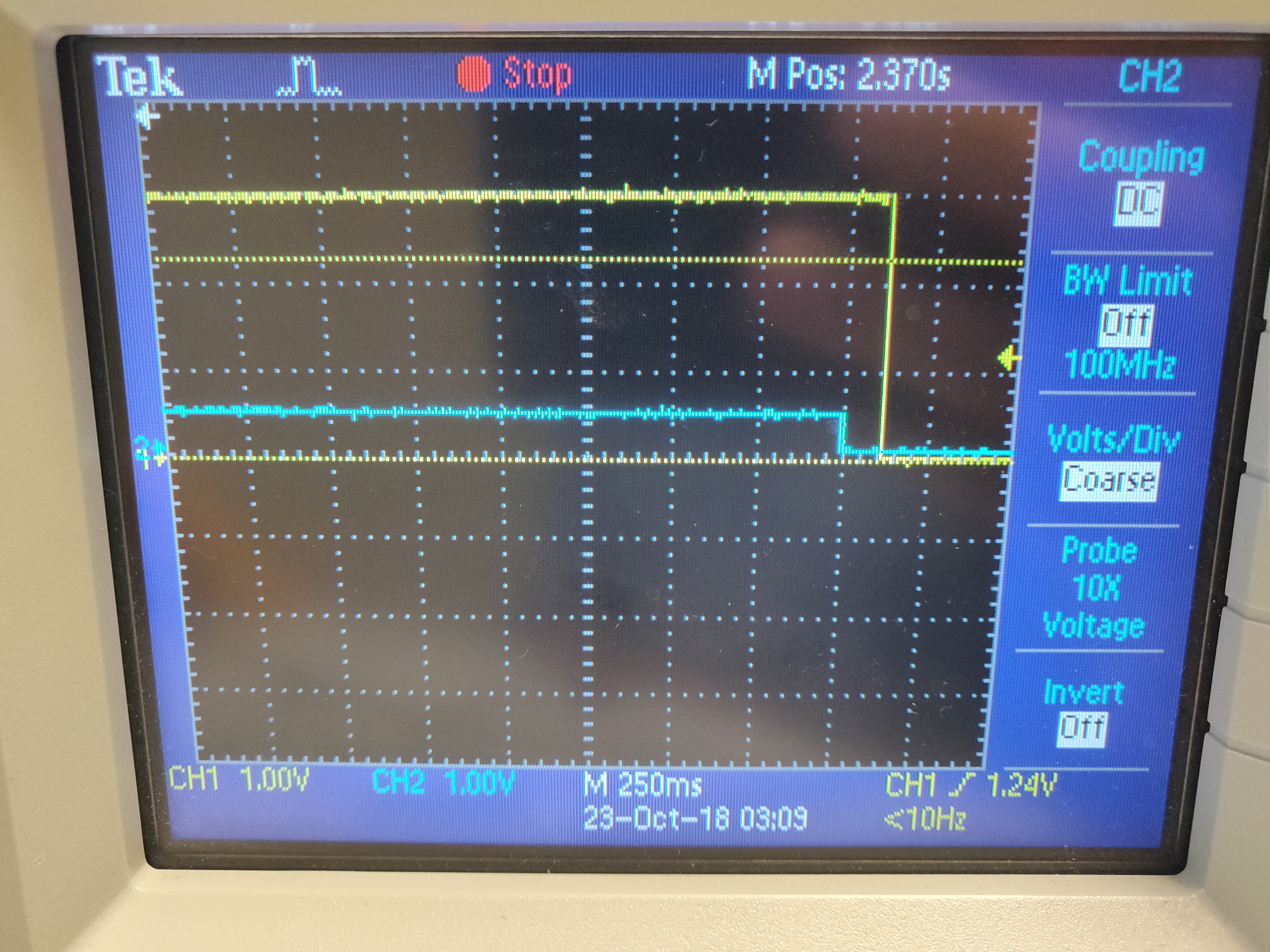
I have observed a failure on multiple devices where there is a residual voltage (~1V) at the output when the load switch is off (ON is low). This is causing a significant amount of current to be drawn across the 65ohm resistor in the active discharge circuit. The output voltage appears to be leaking through the device through VIN. When I reduce the voltage at VIN, VOUT follows lower. So the delta is typically around 2V.

Any thoughts on what would be causing this leakage? Is it the body diode getting damage?

Note that I have confirmed there is no leakage happening through the altimeter itself. 

  • Hi Eric,

    Thanks for reaching out on E2E.

    A few questions to get a better understanding of the application:

    1. Which version of the TPS2292 are you using, are you using one with QOD?
    2. Can you share a copy of the schematic and oscilloscope shots of the behavior?
    3. Have you tried running these tests with the altimeter disconnected? Does the device exhibit the same behavior?
    4. Have you tried replacing the TPS22922? Does replacing the device fix the issue?

    Thanks,

    Arthur Huang

  • Hi Arthur,

    1. Using TPS22922YFPR which has QOD.

    2. Circuit is shown below. Note that VSYS has higher capacitance not shown (47uf).

    The plot below shows Vin (ylw) and Vout (blue) when ON is low (~0V)

    3. I removed the altimeter from the circuit but the issue persists. Same result.

    4. I haven't had an opportunity to replace the load switch because the package makes that difficult.

    If you would like the entire schematic, I can email you offline.

    Thanks

  • Hi Eric,

    Thanks for the update.

    I'm a little confused on the schematic and waveform you provided. Regarding the schematic, are you pulling SDO, CS, and VDD high using the same load switch? What is the reason to pull the data line and CS high? Can you share the part number of the altimeter?

    On the waveform, it looks like the output (blue) is dropping to 0V before the input (yellow) drops. Why is this the case? Are you toggling a pin, or changing a condition?

    Feel free to email me at a-huang@ti.com to share the full schematic.

    Thanks,

    Arthur Huang