This thread has been locked.

If you have a related question, please click the "Ask a related question" button in the top right corner. The newly created question will be automatically linked to this question.

TPS54540: overshoot at start up

Part Number: TPS54540

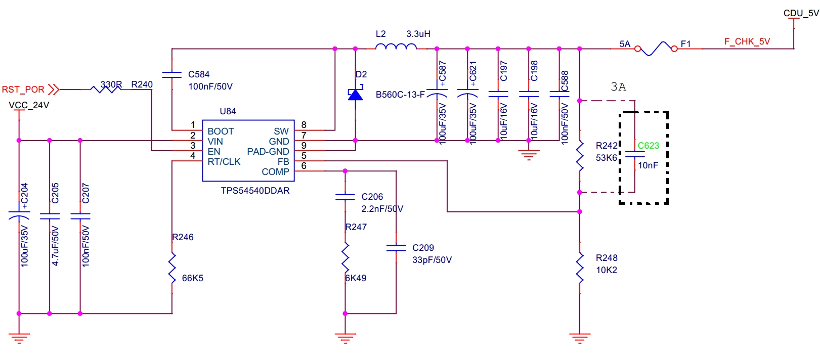
My customer is using TPS54540 to build 24V to 5V buck converter. The schematic is as below:

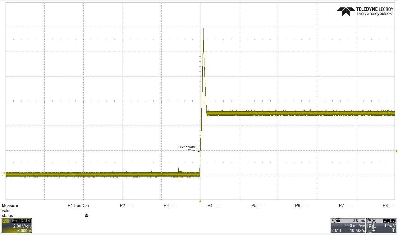
The output 5V has large overshoot at start up shown below:

The customer tried to add C623 in parallel with R242 and the overshoot could be reduced, but the output ripple will be bigger.

Could you please check if the schematic is appropriate and how to reduce overshoot without C623?

  • Hello Howard,
    Can you try changing the inductor to 1.5uH (with C623 removed) and then share results?

    Also what are the output voltage ripple requirements as well as ESR of the output caps? The electrolytic output capacitor may have excessive ESR, or the compensation network may be off.
    Regards,
    -Orlando
  • Orlando,
    thanks.
    I would like to add more information about this case.
    1. At first, the load for this device is sensor A + some other buck and PMIC.
    It can work with no overshoot with the load.
    2. After they upgrade the sensor to sensor B. The rest is the same, they will observe the large overshoot.
    That's because sensor B is capacitor load.
    3. Then they test with load excluding sensor B, and it can also work well.
    4. Then they test with (4 220uF capacitor + some buck and PMIC) as the load, and it will have the large overshoot I show in the original post.

    So the overshoot is caused by the large capacitor(4x220uF) as load. The capacitor is used to simulate sensor B as load.

    So I would ask:
    why changing inductor may help?
    With the new information provided, do you have newer suggestion to deal with the capacitor load?
  • Howard,

    Since the output voltage comes from the inductor supplying current to the capacitor, if the inductor current fell to zero faster the voltage would not rise as much.

    However from your new information I would not change the inductor, but instead recalculate the values for the compensation network (R247, C206, C209) using the largest load capacitance you expect as output capacitance. This should allow the controller to work in all uses, but the transient response could get worse in the other load cases.

    The equations can be found in the datasheet, section 8.2.2.11., just use the maximum Cout in their recalculation. 

    Let me know if that works,

    -Orlando

  • Orlando,

    why in webench the switching frequency range is only 100k-1.42M? 

    In datasheet TPS54540 frequency range is 100k-2.5M, and the frequency of the customer's schematic is 1.44M.

  • Howard,
    The webench menu sometimes doesnt show the correct upper limit but you should be able to put 1440 in for user preferred frequency.
    I ran webench with 1440kHz and 5V 3A output to get a schematic similar to the customer's.

    However changing Cout in webench did not update compensation network for me. Therefore I suggest using the equations to find optimal values.
    -Orlando