This thread has been locked.

If you have a related question, please click the "Ask a related question" button in the top right corner. The newly created question will be automatically linked to this question.

TPS54202: Stability with 1.35V Output Voltage

Part Number: TPS54202
Other Parts Discussed in Thread: , , TPS562201, TPS54308, TPS54339, TPS54239

We are considering the TPS54202 for a new design where we will need four of them, each running from a 15V rail and producing 5V, 3.3V, 1.5V and 1.35V. We have bought several of the TPS54202EVM-716 board to experiment with but are having difficulty getting stable behaviour with the 1.35V output (we are yet to try 1.5V).

The 1.35V rail needs to operate from near 0A load up to around 1.5A.

Initially we took the EVM and experimented with the default 5V setting. We then replaced the lower divider resistor with a 78.7k and 348R in series to produce our 1.35V output, leaving the higher than needed 15uH inductor. The output capacitors 2x22uF match our design (if anything at 1.35V we will have higher capacitance than the dev board would have had at 5V DC bias). We also changed the feed-forward capacitor to 15pF.

The behaviour we are seeing is that:

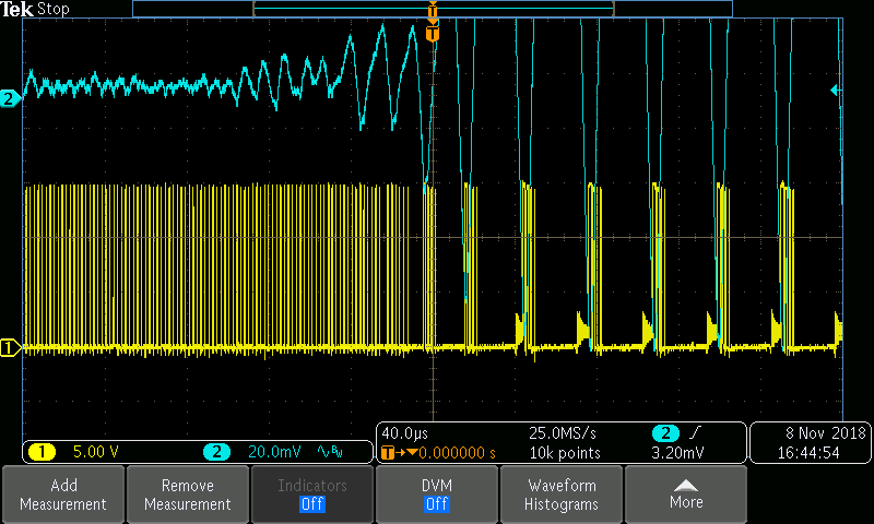
  • With no load the ripple seems reasonable - a 20mV kick every 1 second or so with the pulse skipping mode active
  • From 0A load, ramping up to 300mA we see the ripple ramp up with the load to 112mV
  • Ramping up the load to 2A we see this increase with load up to about 350mV ripple
  • Switching the PSU off and back on with the 2A load present the ripple is <20mV - much cleaner
  • From this point reducing the load in 100mA steps the ripple remains around 20mV until we get to 0.5A when it suddenly jumps up to 350mV
  • The ripple retains this higher level regardless of where the current load is changed
  • Only powering on with the load present and >1.2A gives the lower ripple

This seems like a stability problem - the resulting ripple is not an excessive oscillation but clearly more than we should expect. It also appears with load steps. Sometimes we see low ripple at 20mV then randomly it jumps to 350mV.

We have the same behaviour with the TPS54202H (non spread-spectrum) and when we change the feed-forward capacitor or load capacitance it doesn't seem to make much difference. Increasing the load cap brings the ripple down, naturally, but still more than we can tolerate and this two-state behaviour is not cured. We have also changed the inductor to our calculated value of 4.7uH.

We are have performed stability bode plots which show around 40 degree phase margin, but we are still characterising our test setup and isolation transformer for this measurement. We are working on improving our confidence in this measurement.

I would appreciate any pointers on where we may need to go with this. Ultimately the PSU will be connected to a processor with load step changes, a lot of board distributed capacitance for decoupling. I need to make sure this is a good choice of IC. Alternatively the TPS562201 works perfectly for us but we wanted more head-room on the input voltage.

Kind regards,

Mark

  • The plot below (blue output ripple, yellow switch node) shows when the power supply transitions from around 20mV to several hunded mV output ripple. It was powered on with 900mA load and left. After a few seconds with no external stimulus it changed as shown. It must be on the edge of this instability to trip without load change.

  • Hi,

    What is the load? Is the load constant?

    I recommend the values of L=4.7uH and Cout=66uF/88uF.

    Shawn
  • Hi Shawn,

    Thank you for your reply. We have used two different loads - for the incremental tests we use a TTI LD400 DC Electronic Load. In case of any oscillation with this load we also tested this using wire-wound power resistors.

    We will try with your values, although we have already tried with the 4.7uH as this was our original calculated starting value. We have also tried adding 22uF caps incrementally to the output to see if that helps. For some reason the TPS54202 cannot decide whether it should be pulse-skipping or in continuous switching mode.

    I also found the TPS54308 which we will experiment with - it seems this IC has forced pulse-width modulation mode.

    Mark

  • Hi Mark,

    Yes, TPS54308 is forced CCM, the output ripple is small than TPS54202 at light load.
    Any update, please let us know, thanks.

    Shawn
  • Hi Shawn,

    We tried with 4.7uF and added capacitors to the dev board to cover the 66 and 88uF as you suggest. As expected the larger capacitance did reduce the ripple a bit but we still have this issue where the IC cannot decide if it should be pulse skipping.

    A colleague has done some research from similar issues people have reported with other ICs - this suggests it could be something to do with the current sensing that determines whether to enter light-load mode or not. It seems sometimes it is doing this when it shouldn't hence the larger output ripple.

    We have the TPS54308 on order to experiment with. I have also ordered dev boards for the TPS54239 / TPS54339 as these have D-CAP2 which should be better in our application.

    It would be nice to know why the TPS54202 is struggling at this output voltage though rather than just use a different IC to solve the problem. We have spent a fair bit of time looking into this but I wonder if it is a limitation of the IC?

    Thanks, Mark

  • Hi,

    For TPS54202, it is designed for high efficiency at light load, but the ripple is larger because of the skip pulse mode. If you care about the output ripple and there is no requirement for efficiency, you can use force CCM device, such as TPS54308.

    Could you please share the waveforms (SW, VOUT)with L=4.7uL, Cout=88uF?

    Shawn
  • Hi Shawn,

    I will work on getting the waveforms added to this thread - hopefully for a given load we can provide an example of when switching normally and low ripple and when pulse-skipping. This might take a day as we have another project on the go.

    I guess this ripple seems more extreme because of its size relative to the output voltage. It seems from this investigation we have learned that if we want low output voltage and low ripple from no load upwards we do not want a converter with light-load efficiency modes and need FCCM.

    Mark
  • We are still working on this. Selecting a different IC works around the issue but we would like to try and understand why the original selection is not performing well.
  • Hi,

    As I mentioned, if the device is eco-mode, the switch frequency is reduced at light load to get higher efficiency, but the ripple is larger. If the device is FCCM, the frequency is the same with CCM, the ripple is small, but there is a bad efficiency at light load.

    Shawn