This thread has been locked.

If you have a related question, please click the "Ask a related question" button in the top right corner. The newly created question will be automatically linked to this question.

LMR23630-Q1: Bypass capacitors at the load

Part Number: LMR23630-Q1
Other Parts Discussed in Thread: LMR23630

Hello TI,

We are using the LMR23630-Q1 to step down 12V to 3,8 for a GSM/LTE modem. The WeBench design recommends a 200 uF cap with ESR less than 30 mOhms at the output pin of the DC/DC convertor. The reference design for the GSM modem recommends two 100 uF bypass capacitors at the VCC pins of the chip. 

What should I be wary of here? The trace from the LMR23630 to the modem would be around 5 inches long. 

1) Should the bypass capacitors at the modems VCC also be low ESR? 

2) Should I also  consider the bypass capacitors at the modem in determing the stability of the output of the DC/DC. Should I stay below the upper bound mentioned in the WeBench design?

  • Hello Pradeep,

    The total capacitance on the output (local to the DC/DC and at the load) should be considered for stability calculations. In general, low ESR caps provide the best transient response. One option is to place some capacitance at the VCC of the modem and the remainder near the DC/DC converter. Also, route the connections from the converter to the load with wide copper planes, placing VOUT and GND planes on adjacent layers to achieve a bus structure with low parasitic inductance.

    Regards,
    Tim
  • Hello Tim,

    Thank you for the comprehensive answer! That helps a lot.

    I have a related question that I hope you could help me with. 

    Our power stage includes two LMR23630s, one stepping down to 3,3V and the other to 3,8V.

    To reduce the conducted emissions I have added the following LC filter at the input to the convertors. 

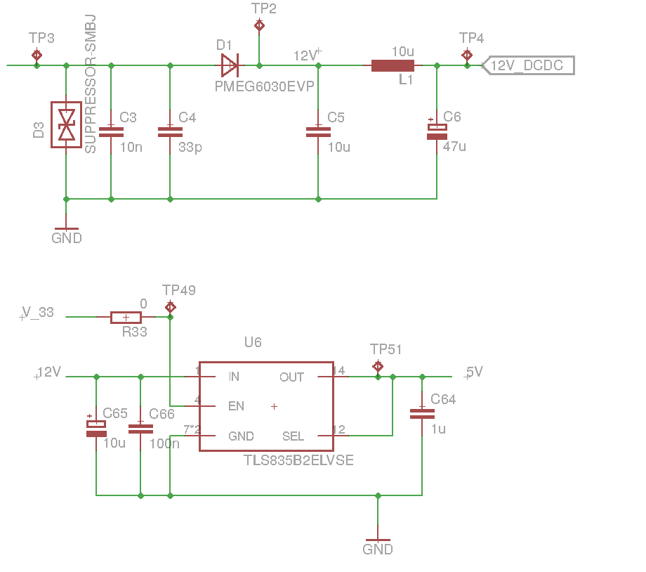
    I have an additional 5V LDO stepping down from 12V where I need to add a high ESR aluminium electrolytic cap to smoothen out the input transients. 

    Show in the below schematic are the nets 12V and 12V_DCDC.

    Is it the correct decision to connect the LDO input to the '12V' net and not the 12V_DCDC net, before (or after if considered from the point of the DC/DC) the LC filter?

    Or will this high ESR bulk cap have an effect on the LC filter? 

    Thank you!

  • Hi Pradeep,

    I recommend connecting it after the reverse protection diode at the 12V_DCDC terminal. Then maybe you can use one electrolytic cap. A high ESR electrolytic is generally required at that point anyway as it provides parallel damping of the input filter.

    Regards,
    Tim
  • That makes sense.. However, if the LDO is positioned quite a few inches away from the input filter, then can I add a 10uF at the input of the LDO? Or does having two bulk capacitors at the 12V_DCDC terminal reduce the high ESR required there?
  • Hi Pradeep,

    I think a ceramic input cap should be sufficient for the LDO. One bulk electrolytic is typically enough.

    Regards,
    Tim
  • Hi Pradeep,

    Since there's no further activity here, I'll go ahead and close this out.

    Regards,
    Tim