This thread has been locked.

If you have a related question, please click the "Ask a related question" button in the top right corner. The newly created question will be automatically linked to this question.

UCC28950: Application Circuit

Part Number: UCC28950
Other Parts Discussed in Thread: TIDA-00200

Hi,

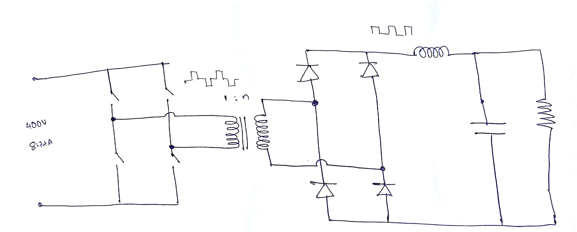
I am designing a 60V, 3.3kW Full bridge DC-DC converter for building a Li-ion battery charger. I am using UCC28950 Phase-Shifted Full-Bridge Controller for controlling the primary side MOSFET's. I am using the following configuration of full bridge converter as shown in the figure. 

I would like to get an expert opinion on some of the queries that I have:

1) What are the factors that will affect the core saturation of the transformer? Does duty cycle of primary input signal play any role in saturation since its an AC waveform?

2) I would like to implement the CC-CV charging technique. Can I use the feedback circuit that is given in TIDA-00200  application note to achieve CC-CV charging with UCC28950 Controller?

3) Does the Load current affect the ZVS operation of primary side MOSFETs?

4) Apart from reducing losses what are the advantages if I use a center-tap secondary with only 2 rectifier diodes other than Bridge rectifier in the secondary side?

5) How will the leakage inductance of the Transformer affect the ZVS operation?

  • Hello Sonu

    1/ The core will saturate if the volt*second product exceeds the capability of the core. Basically, the flux density is B = VT/NA N is the number of turns, A is the core cross section, V is the voltage across the winding and T is the time for which the voltage is applied. In a given transformer at a fixed input voltage V, N and A are fixed so the flux density becomes a function of time (or duty cycle). Having equal positive and negative duty cycles ensures that the positive and negative flux changes are balanced out. There are a few other small things (gaps in the core for example) but they don't really apply to the PSFB.

    2/ The CI/CV technique used in TIDA-00200 is the usual one and will work well. U3A is the CV error amplifier and U3B is the current error amplifier.

    3/ Yes, the primary current is used to drive the ZVS transitions and of course the primary current is a function of the load current. The result is that ZVS is easily achieved at full load but becomes more difficult at light loads - depending on the details of the design. You can find some relevant material at training.ti.com/topology-tutorial-what-phase-shifted-full-bridge and training.ti.com/phase-shifted-full-bridge-psfb-vs-full-bridge-llc-fb-llc-high-power-dcdc-conversion

    4/ The choice of secondary circuit is complex. At 60V out you should probably go for a single winding secondary with a full bridge rectifier - using SRs or Diodes. the UCC28950 has SR drives that can be used (with suitable high/low gate drivers) to control the SRs. Don't assume that going to a centre tapped secondary will automatically reduce losses - you do get a reduction in diode Vf losses but at any given time only half the secondary is carrying current. The Voltage stresses on the diodes are higher with the CT too and there is an inherent tradeoff between Vf and Vrr in a diode - the higher Vrr diodes will have a higher Vf too. Finally, the half of the secondary winding that is not carrying current may be contributing to ac losses due to skin and proximity effects. None of this is simple - your choice of a full bridge secondary is reasonable.

    5/ One of the nice things about the PSFB is that the leakage inductance acts as an energy source to help drive the ZVS transition. This means that the energy in the leakage inductance does not get lost as heat. The Excel calculator on the UCC28950 product page will help guide you to decide on the correct amount of leakage inductance. Note: the calculator assumes a center tapped secondary - although this won't affect the primary circuit results.

    Regards
    Colin