A related question is a question created from another question. When the related question is created, it will be automatically linked to the original question.
If you have a related question, please click the "Ask a related question" button in the top right corner. The newly created question will be automatically linked to this question.
I ask a really specific question. Why do I need to share my design? How do I compensate for leakage induction in the transformer in a opto coupler less design? specific for the UCC28701. Is there any documentation about it.
I will have to understand what component values you have chosen for sensing the aux winding voltage, output cap, regulation voltage, and transformer turns ratio, your input/output spec etc to review your design first. If the output is in regulation then we will have to look at the aux winding voltage to understand if this leakage in the aux winding is having a significant impact to cause a false knee detection and then work our way towards the answer.
The behavior you are noticing might be because of several reasons like the load sharing between the aux and sec winding, leakage on both the windings, ESR of the output caps etc.
I do not have a plug and play answer for you if that is what you are expecting.
Regards,
Sonal
I have some experience designing power electronics. I use the UCC28701 for a 24V->5V supply while using a POE transformer. So that is a not the intended use. But because "I know what i'm doing" This is a working design but because of design tolerances in the transformer I got some issues.
The UCC28701 oversimplify the design process in the datasheet. So If you design it outside it for it intended use. You are on your on. That should not be a problem But I need information how to adjust the voltage control loop So I can stay within the save operation area.
So If TI is unable the rather generic question how to compensate for leakage in inductance in a opto coupler less design.
Maybe you can help me with the following question:
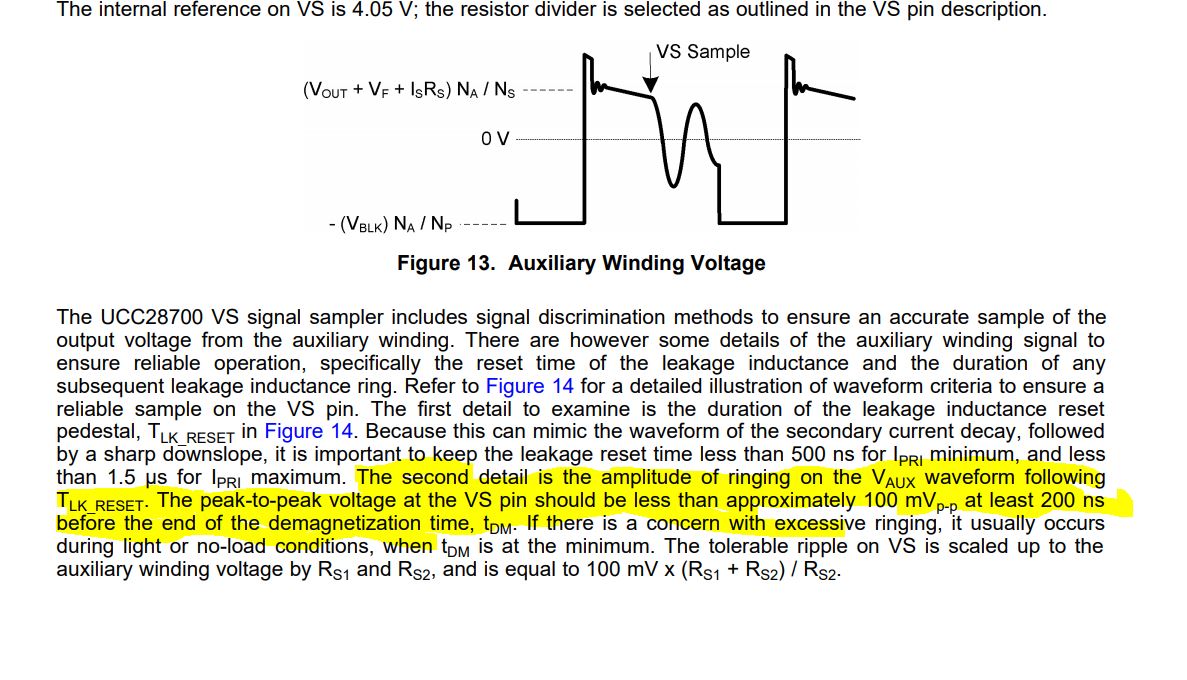
UCC28701 datasheet page 9. The Vs ripple is needed to generate the timing signals for the the duty cycle.
- How does the " control law " block generate this signal?
- How much delay can I add allowed before stability becomes an issue?
Thanks for the information. This also answer my question. Vs sample is at the end of the energy transfer cycle so any transfer delay introduced by leakage induction is already passed.