This thread has been locked.

If you have a related question, please click the "Ask a related question" button in the top right corner. The newly created question will be automatically linked to this question.

BQ2057W: STAT output question

Part Number: BQ2057W
Other Parts Discussed in Thread: BQ2057, MSP430F5529

Good evening....

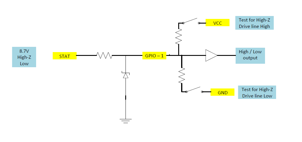
I am using a BQ2057W (8.4V) part and want to take the STAT output to an MSP430 input....The MSP430 is a 3.3V part.....The STAT will be driven, low, high or tri-state.....I would like a cheap solution that will translate for me to the MSP input....According to the BQ datasheet STAT will be at a minimum of VCC-0.5V when it is high....My VCC is about 8.7V....This means STAT high will be about 8.7V to 8.2V......

I am well aware of using I2C MOSFET translation and am sure I can make it work with these voltages unfortunately using this solution with the BQ2057 datasheet Figure 11 on how to interface to read a tri-state won't work.....Does anyone have any ideas on this one?

Thank you

Steve

  • Hi Steve
    The I2C MOSFET translation is what I would recommend this would have a low part count and should be pretty cheap.

    Figure 11 needs to be updated.
  • Steve,

    Can you add a zener diode and resistor to clamp the STAT output voltage to that of your MSP430? The zener clamp woulI also recommend a an RC filter as the STAT output of this device has been known to jitter in the 10kHz range.
  • Bill...

    Not sure I completely understand where you are going.  Using an I2C mosfet translation as they do in NXP AN10441, how would I isolate the resistor in Figure 11 in the BQ datasheet from the low voltage resistor on the mosfet circuit.  Example...STAT pin is driven 'HIGH'....MSP PIN register see's a HIGH BUT the question remains is it driven or is it floating so we must write to the output to drive the PIN line...In writing a LOW to this register is going to create a voltage divider between the resistor in FIG 11 and the low voltage gate-source resistor thus potentially violating the thresholds of the MSP??

    Am I missing something here?

    Thanks

    Steve

  • Jeff...
    Thanks for response....Not a huge fan of the zener as it will continually draw and waste current from the LiPo to regulate....
  • Sorry Steve
    I misinterpreted your statement "I am well aware of using I2C MOSFET translation and am sure I can make it work" as meaning that you had a solution using mosfet BUT were looking for something lower cost.

    I have discussed this with another engineer familiar with MSP430 and have some ideas, more later.
    Can you use two GPIO and some code?
  • Bill....
    I can afford two I/O as in Figure 11 on BQ datasheet....
    Looking forward to seeing your solution.....
    Thx.
    Steve
  • Hi Steve

    I have been looking at trying to diode clamp the STAT pin to MSP430 VCC to give a more accurate limit on the voltage.  But down side of this approach is the input voltage will now be VCC + diode drop which would still be too high.  Using the MSP430F5529 as a guide the input voltage is limited to VCC + 0.3V.  So this is a no go and will have to go back to the zener approach recommended by Jeff.

    Also input from the MSP430 contact is the input pull up and pull down can be switched in and out under control of the code.  This would reduce GPIO to one for the test of High-Z condition.  

    Sketch of proposed circuit below.

    Valid High input for the input (F5529) is 2V min with a max of VCC +0.3V, zener would need to limit voltage in that range.