This thread has been locked.

If you have a related question, please click the "Ask a related question" button in the top right corner. The newly created question will be automatically linked to this question.

TPS65919-Q1: How to calibrate the ADC

Part Number: TPS65919-Q1

Hi,

We are using TPS65919-Q1 in our project. We have to calibrate ADC channels.

I go through the slia087a.pdf document for ADC calibration which is available in attachment.

In this I have some doubt ,

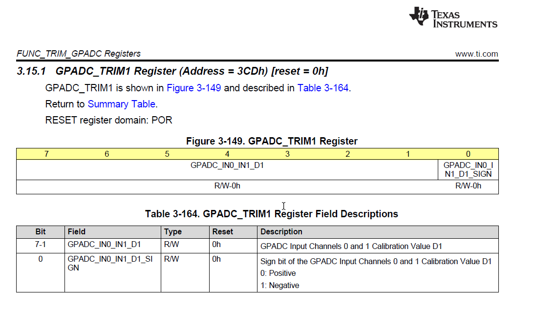
1) Initially GPADC_TRIM1 and GPADC_TRIM2 register values are zero. Then how to calculate Gain and  offset error using below formula ?

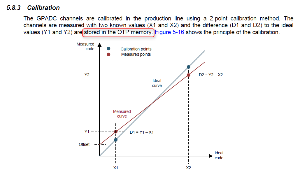
Gain k = 1+ (D2 - D1)/(X2 - X1)  and  Offset  b = D1 - (k - 1) * X1

In this X1 and X2 are given voltage in ADC value and D1 and D2 are GPADC_TRIM1 and GPADC_TRIM2 register values.

2) And after calculation of gain and offset how to use it ?

slia087a.pdf

  • Arun,

    How are you reading the trim registers? Can you detail which registers you are reading?

    Thanks,
    Nastasha
  • After changing below register value as 1, now I am getting GPADC_TRIM1 and GPADC_TRIM2 value.

    SPI_PAGE_CTRL - 0x7F (Page 1).

    Now my doubt is

    X1 and X2 values always i should take as 2064 and 3112 ???

    after calculating Gain and Offset error what have to do ? With help of this how to calibrate ?

  • Hi,

    Please help me to calibration.

    Thanks
    Arun
  • Hi,

    Is it possible to modify the GPADC_TRIM1 and GPADC_TRIM2 register values ?

    If possible how ?

    Thanks
    Arun
  • Arun,

    You cannot modify the trim registers. Also, the trim registers should not read 0. Can you share the details of how you are reading the trim registers?

    For this device, you will use 2064 and 3112 as your X1 and X2.

    Thanks,
    Nastasha
  • Hi Nastasha,

    I am able to read the TRIM register values. I am getting values TRIM1 as 48 and TRIM2 as 78. Actually we want to calibrate the ADC channels for our voltage range i.e different X1 and X2 values.

    So after calculating Trim values(D1 and D2) for our voltage values(X1 and X2), how to update in to TRIM register?

    If it is not possible means, should I use only whatever u calculated TRIM values?

    Please reply as soon as possible.

    Thanks and Regards

    Arun

  •  Hi Nastasha,

    In Register description document TRIM registers are mentioned as read and write. You can see in attachment. But TRIM registers value is not modifying.  

    Is there any procedure need to follow to modify the TRIM registers? Please help me.

    Thanks and Regards

    Arun

  • Arun,

    You cannot modify the trim registers. These are fixed. There are 2 ways to calibrate the GPADC:

    1. Use the formula that is in the app note/datasheet. This is what you are currently using. This formula is based off collecting two data points and creating a linear relationship between them for calibration.

    2. If you want different data points or more data points, you can do your own calibration. This does not make use of the trim values. Rather you take data points from the GPADC at known values and build your own plot. For example, if you are calibrating the current monitor channel, you would read the GPADC at 1A, 1.5A, 2A, 3A, etc. and plot the 8 bit code to build your own linear or quadratic relationship.

    Thanks,

    Nastasha

  • Hi Nastasha,

    Thanks for your information.

    While receiving product from ti team, is that calibrated one?

    If not calibrated,  after calibration Is it possible to store in to OTP memory?  How to write in to OTP memory?

    Thanks and Regards

    Arun

  • Arun,

    You cannot write into OTP memory. TheD1 and D2 that are stored in memory are trim values and should not be changed. The units shipped from TI will already have these trim values stored. Then you can use the suggested X1 and X2 values for calibration. If further calibration is required, I recommend not using the trim values and manually running tests to correlate the output read from the GPADC and the expected output (for example the known load current if you are testing the current monitoring channel).

    Note: for the current monitoring example, the GPADC is not very accurate for currents under 500mA.

    Thanks,
    Nastasha