This thread has been locked.

If you have a related question, please click the "Ask a related question" button in the top right corner. The newly created question will be automatically linked to this question.

UCC28061: UCC28061 issue

Part Number: UCC28061

Hello,

My customer got urgent issue during 320W application test using UCC28061.

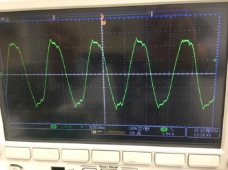
In the prototype test, it was found that the PF value was unstable and accompanied by a large sound during 120Vac input, if the input voltage increased or the load decreased, the issue was gone. The input current waveform is distorted near the peak when the audible noise is detected, as shown in Figure 1.

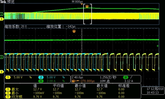
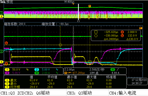
Further testing found that the two-way drive is no longer out of phase when the input current waveform is distorted, as shown in Figure 2 below.

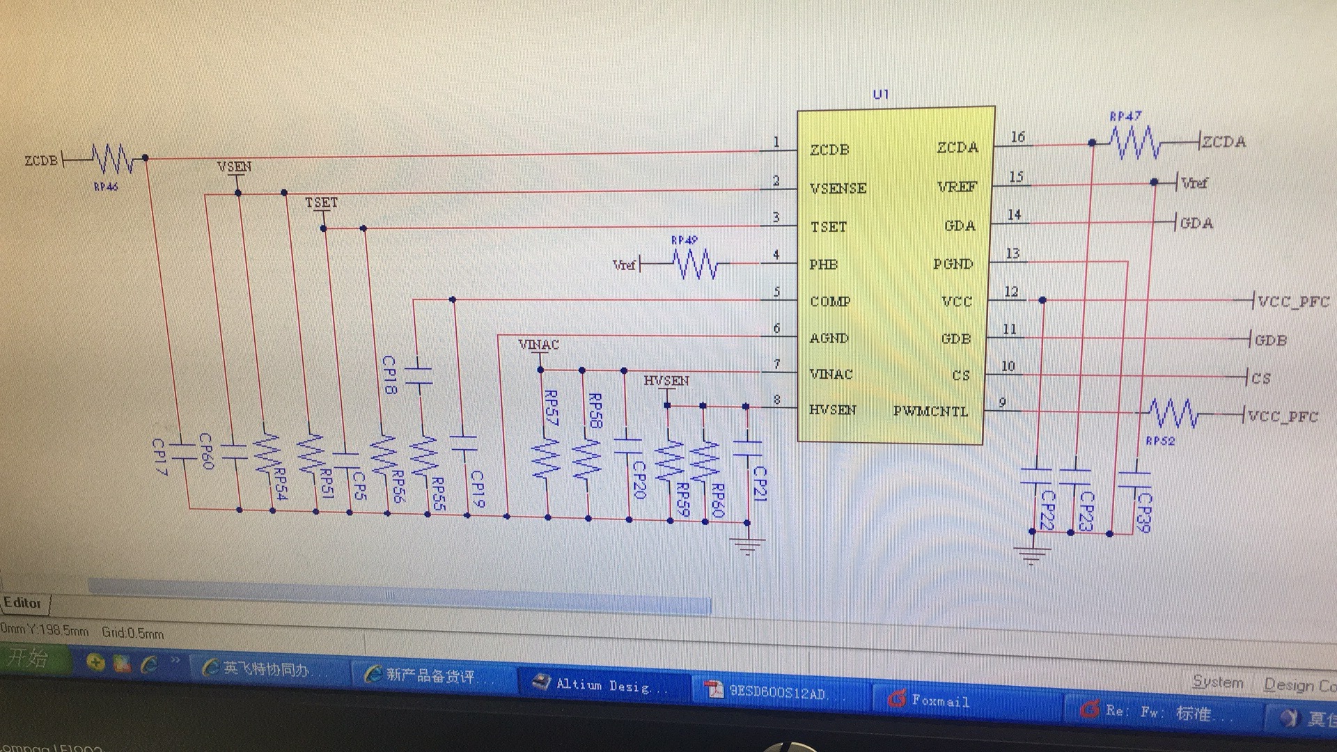
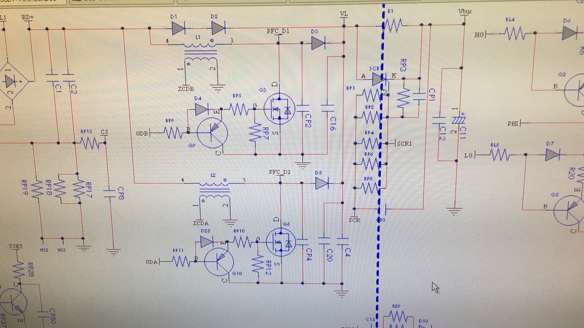
And the schematic is as below, the transform has been checked and it's not enter into saturation status.

  • Hello Leo,

    May you please share their design spec, output voltage, inductor selection and turns ratio.
    What is the value of current sense resistor?
    What is the resistor value connected to PWMCNTL pin and what happens to the voltage at this pin at high load condition?
    It would also be interesting to look at the ZCDA/B pin waveform and what happens when you see this issue?

    Regards,
    Sonal
  • Hello,

    Input voltage: 90-305Vac

       Output voltage: 420V

       Inductance parameters: 320uH 70:12

       Sampling resistance: 0.03/0.04

       PWMCNTL pin : 10K resistor is connected to the stable level Vcc, no change when abnormal

    ZCD waveform is as below channel 1, looking forward to your reply!

  • Hello Leo,

    I reviewed the waveforms and think that you might be hitting over current limit which is CS of -0.2V or less.

    Durring initial power up or after peak current limit protection is triggered both phases of the UCC28061 will startup and within a couple of switching cycles they will come out of phase.

    You mentioned this occures at 120V AC and will be removed when either the input voltage is increased or the output current is decreased. Since P=VI increasing V will decrease I, so this sounds like peak current limit. If is continuousely hitting peak current limit this will be audible.

    Rp13 might be too large for the power level and effiency of your converter. You could try decreasing its value to see if it resolves the issue.

    Sometimes noise on the CS pin can cause false peak current limit triggering. You could try adding a capcitor to the CS pin. There is a place holder in the schematic for one.

    Regards,

    Mike
  • Hi Mike,

    Thank you for your suggestion.

    CS pin testing voltage is 140mV, Rp13 is 100ohm, capacitor is already added, it's 0.01uF. Is there other possibility?

  • Hello Leo,

    It did seem like you were hitting over current.  The other option is that you hit OVP.  You might want to check to see if that is the case.\

    Regards,

    Mike

  • Hi Mike,

    Actually we have checked the OCP, it's not the reason, either is OVP.
  • Hello Leo,

    If it is not OVP or OCP the only other thing could be ZCD false firing. This will occur when the input voltage is larger than the output voltage. This could explain why the drive pulses lign up. But you would only see this durring power up.

    Could you go discuss deeper what you mean by instability? Does it show up as exesive output ripple voltage or audible noise?

    Regards,

    Mike

  • Hi Mike,

    Thanks for your comments, i will have a double check again, the instability means the mis-phase of GDA & GDB, just as the waveform I show above, and also audible noise is heard.
  • Hello Leo,

    Did you resolve the issue?

    Regards,

    Mike