This thread has been locked.

If you have a related question, please click the "Ask a related question" button in the top right corner. The newly created question will be automatically linked to this question.

UCC28600: How to set the primary side current of optocoupler in the flyback module?

Part Number: UCC28600
Other Parts Discussed in Thread: TL431

Hello!

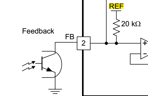
It's a new question of UCC28600 QR detection failure. I feel strange about the FB-pin current, the optocoupler primary current IF was about 25 mA at no load.

Check the CTR-IF curve of TLP521, it seems like the secondary current IC was more than 250uA(VREF/20K).

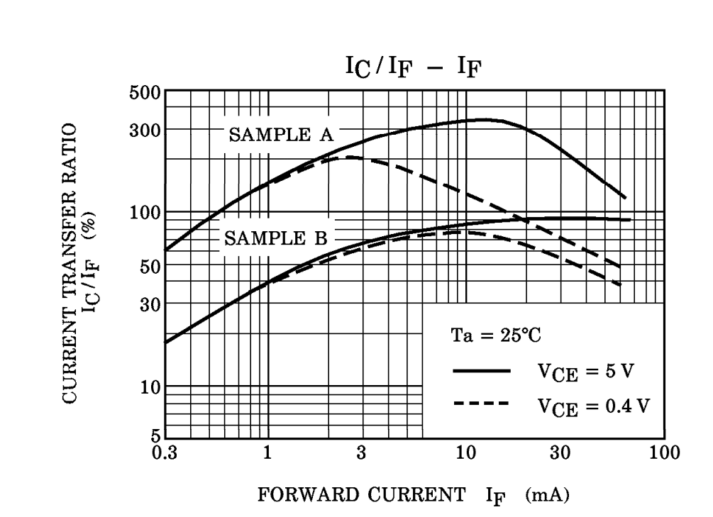
And at 1A load, IF was about 8 mA, IC was still larger than 250uA...The whole process of increasing load to 2A, the circuit had stable 24V output.

But when I reduced IF by presuming  IC=250uA, the circuit was unstable at no load, TL431 didn't work, the output voltage was about 35V(24V is the goal).

Is there any supplementary current adding to FB-pin? I check some Ti recommended design of UCC28600, IF is lese than my design but I am not aware of the specific design rule about IF.

  • Hello Airut,

    Thank you for your interest in the UCC28600 QR controller, and your question about optocoupler CTR.

    The CTR curves of this optocoupler, and any optocoupler, indicate the diode forward current (IF) needed to obtain a certain collector current (IC) under the stated test conditions. There are 2 types of curves: IC on y-axis, and CTR on Y-axis, (both with IF on X-axis) but sometimes a vendor may publish only one of those curves. The CTR curves are cumbersome to interpret, since one must perform some mental math to determine the specific IC for a specific IF. In most designs, the designer needs to know what specific IF is necessary to achieve a specific IC.

    In the case of the TLP521, the data sheet also provides a set of direct IC/IF curves, which are easy to interpret.
    An optocoupler does not "push" current, in the sense that if you feed 25mA into the diode, it forces 25mA into the collector.
    Instead, consider that it can "allow" up to (CTR*IF) amount of current into the collector, depending on the collector network impedance.
    Since the UCC28600 FB input has a 20K resistor pulled up to an internal 5-V REF, it can only source up to 250uA; no more.
    Excess IF will simply saturate the optocoupler's transistor.

    The control of the UCC28600 is such that full power is delivered when the FB current (Ifb) = 0uA and virtually no power is delivered when Ifb > 220uA. The UCC28600 enters its "Green-Mode" state when Vfb falls below 0.5V. Therefore the optocoupler transistor must saturate at ~220uA to allow the controller to enter this state. From the TLP521 IC/IF curves, it shows that Sample A needs only IF = ~0.35mA to achieve this, while Sample B needs IF = ~0.75mA. This indicates that the spread of optocoupler CTR at this low IC level ranges from ~62% to ~29% at 25C ambient temperature. It is prudent to design for the reduction of CTR at higher temperatures. According to another IC/Temp curve, CTR can reduce again by 50% for ambients >80C. So the shunt regulator controlling IF must be designed to be able to sink 0.75/50% = > 1.5mA in order to saturate the opto-transistor at 220uA at ~80C.

    The circuit components around the shunt regulator and the optocoupler are designed to be able to provide at least this current, plus the bias current needed by the shunt regulate itself, when operating in the no-load condition (no external load).

    Please consult this design guide for working with the UCC28600 feedback loop compensation network: www.ti.com/.../slua671.pdf

    I hope this helps to resolve your issues.

    Regards,
    Ulrich
  • Thank you for your comprehensives reply!
    I understand the method of setting IF now, but the problem is that I can't get a stable output while IF is 0.75mA using TLP521, it needs to be more than 8mA that makes a stable 24V output at no load. Otherwise, TL431 can't work properly and output will be larger than presetting one with IF=0.75mA. And the frequency is clamped to 40KHz even at 24V/2A load. My transformer is 600uH(Np:Nb:Ns=30:5:10), although larger than calculated one but still fit in 220VAC INPUT situation.
    Rovp1= 166.8K Rovp2=42.9K
    Rcs=0.375 Rpl=1K
    Rfb=620 Rbias=1K
  • I may know the problem, the duty cycle is less than calculated one even in 2A/24V load. 

    Np:Nb:Ns = 30:5:10

    The calculated value = (24+0.6)*3/((24+0.6)*3+320) = 18.7% 

    But the actual maximal duty cycle  is only 11.8% with 220VAC input.

    The duty cycle is extreme small at no load condition, the secondary output is lower than expected value and it can't make a effective feedback to FB-pin with Rfb set assuming the output is larger than 24V.

    The improper transformer which has larger Lm and enough designed rated power may be the key to the problem, it can store enough energy with less duty cycle of  Mosfet switching.

  • Hello Airut,

    I'm checking in about this open issue.
    Do you consider it to be resolved or so you still need more support?

    Regards,
    Ulrich
  • Ok, consider it resolved, I will redesign my transformer and try again.