


Hi experts,
I'm trying to design a down-chopper using the UCC3802. I'm quite familiar with the down-chopper basics, but I am having trouble understanding the UCC3802 itself. I've tried reading the datasheet for it but it's overwhelming for me. I know that you can "program" the frequency with a small RC network, and that the duty-cycle is unprogrammable because of the internal resistor.
I'm wondering how I could "program" the UCC3802 for a wishful 15V DC on the output of my down-chopper, with an input between 280 and 700V DC. (note: the circuit does not need to be isolated)
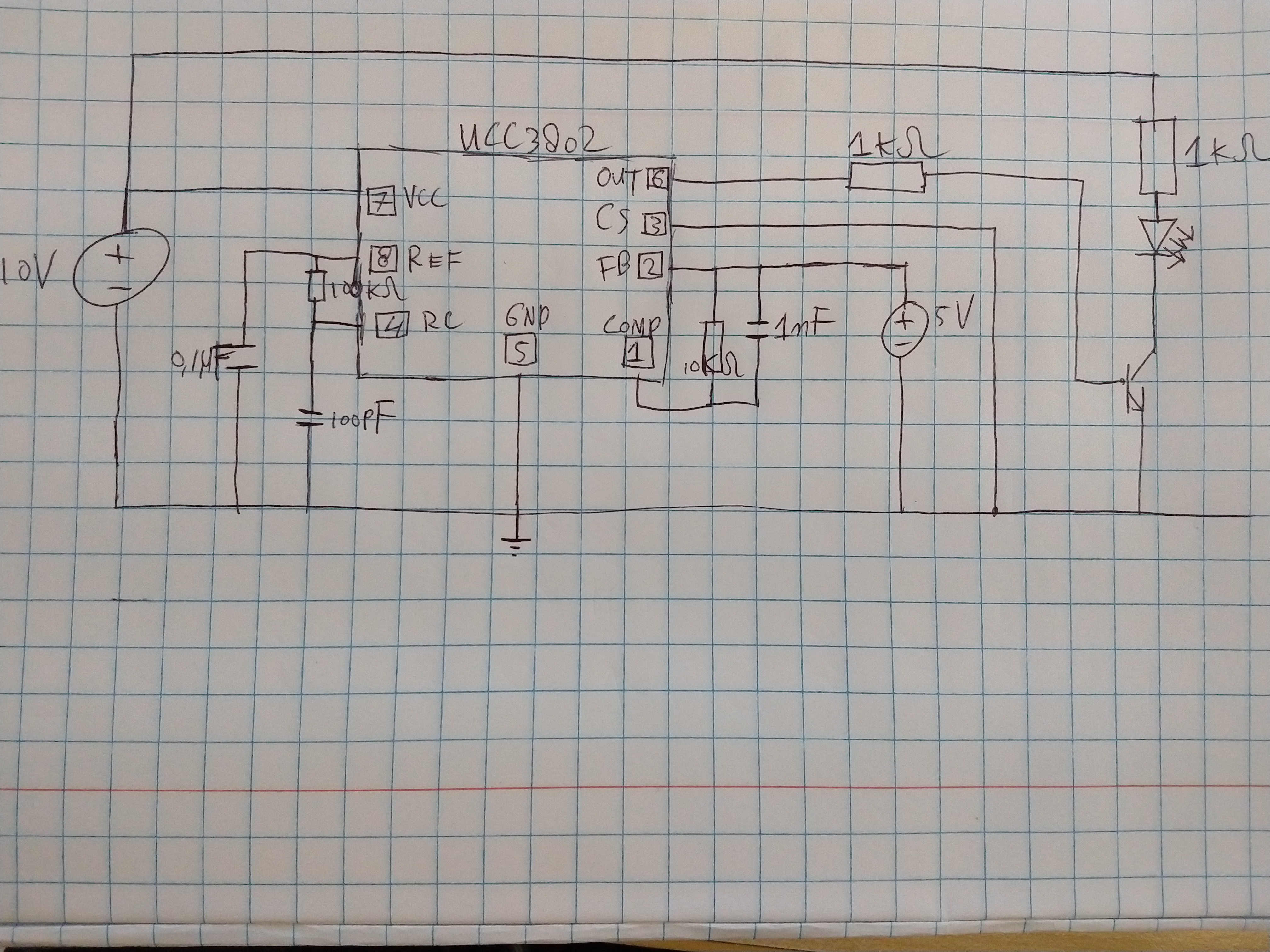
I've been making a test circuit, where I'd like to see the pulses on the output of the UCC3802, with a frequency of 100kHz. ( see attachment ),
In the testcircuit I use 10V DC to supply the chip, and I attached a 5 V DC source to the FB pin. So I'd expect a signal of 100kHz and a duty cycle of 50% on the Output (6). Sadly I only measure noise with my oscilloscope.
Could anyone tell me what I'm doing wrong?
Kind regards,
Bryan Boonekamp
Bryan Boonekamp

