This thread has been locked.

If you have a related question, please click the "Ask a related question" button in the top right corner. The newly created question will be automatically linked to this question.

REF34-Q1: Is this power-up behavior correct?

Part Number: REF34-Q1
Other Parts Discussed in Thread: TINA-TI, REF3450

Hello Team,

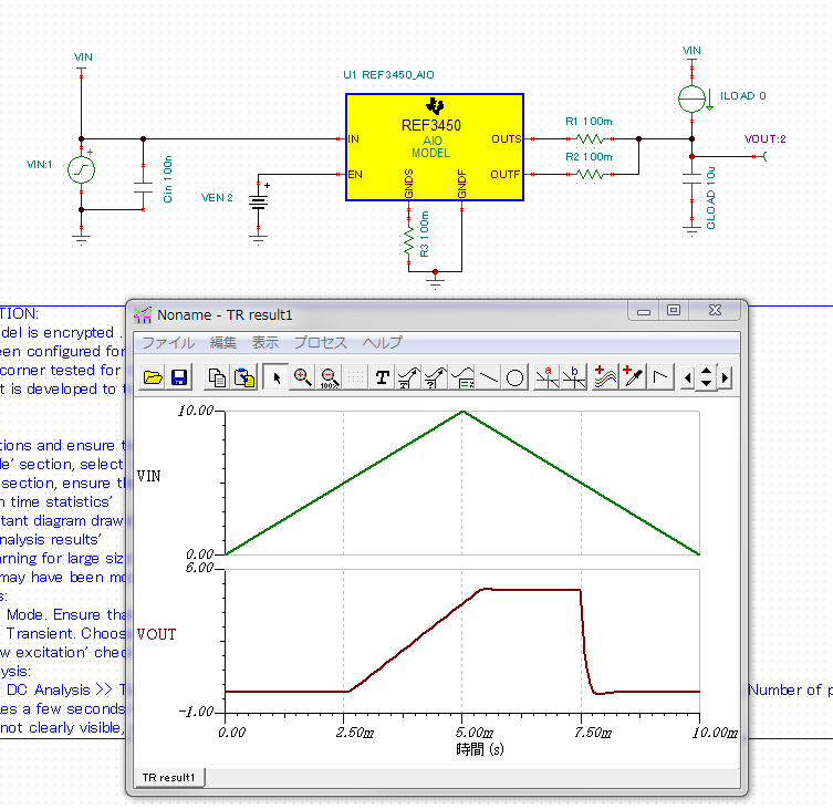
I performed TINA-TI simulation for REF3450-Q1.

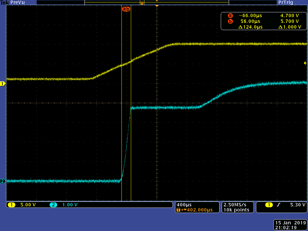
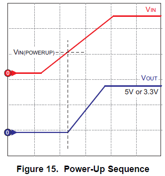
Q. As we can see in the waveform, when the Vin increase gradually, the Vout start increasing from @Vin=5V. Is this behavior correct? VEN is 2Vdc.

Q. Customer's requirement for this device is to start increasing Vout from Vin=4V. Is there any solution or other good device for that?

Thanks,

Yuta Kurimoto

  • Since this is a linear device, the 5.0V references requires 5V + the dropout voltage for any output voltage. I assume the model is defined from this datasheet specifications.

    I would say this would be normal or expected behavior, but after testing this device on my bench,I started to see that the device started tracking the input at around ~3V. Even though the the simulation does not support the customer's request, real life application does.

    Thanks,
    Ethan
  • Hello Ethan,

    Thanks, I understood. I know the 5V references requires 5V+ dropout voltage. So in case input voltage is less than 5V, the reference just tracks the input.

    Customer's question is below.

     Q. when the reference start tracking the input? can you show the threshold voltage?

    I think it's not written in datasheet so I would appreciate if you can perform simulation or you can explain why the tracking start from 3V

    Thanks,

    Yuta Kurimoto

  • Hi,

    Below are two scope shots of the input and output of the REF3450. Channel 1 (yellow) is the input voltage, and channel 2 (blue) is the vref output.

    The first scope shot is a function generator input with a 10V /1ms slew rate. As you can see here the quick slew rate causes the REF3450 to start rising around ~5V.

    The second scope shot is from a bench power supply that has a much slower slew rate. The REF3450 starts rising around the ~3V I measure previously.

    Hopes this helps,

    Ethan

  • Hello Ethan,

    Thanks. Now I'm checking the actual input slew rate of customer's system. If their slew rate is low, it would be good.

    Yuta Kurimoto
  • Hello Ethan,

    Q1. Customer thinks the Vout threshold differences are caused by not the input slewr rate but the IC's response time. Can you get the data like below?

           And is there any data of IC's response time?

    Q2. In your measurement results, the Vout become flat at 3~4V and then start increasing again. What is the reason of this behavior?

    Thanks,

    Yuta Kurimoto

  • I re-posted.

    Hello Ethan,

    Q1. Customer thinks the Vout threshold differences are caused by not the input slewr rate but the IC's response time. Can you get the data like below?

           And is there any data of IC's response time?

    Q2. In your measurement results, the Vout become flat at 3~4V and then start increasing again. What is the reason of this behavior?

    Thanks,

    Yuta Kurimoto

  • Hi Yuta-san,

    I am currently looking into this with my design team. I will get back to you shortly.

    Thanks,
    Ethan
  • Hello Ethan,

    Thanks for your support. How about the feedback?

    Yuta Kurimoto

  • Hi Yuta-san,

    Thank you for your patience. I have sent you an email regarding my feedback.

    Thanks,

    Ethan