This thread has been locked.

If you have a related question, please click the "Ask a related question" button in the top right corner. The newly created question will be automatically linked to this question.

LM2733: Large output ripple when large output C connected

Part Number: LM2733

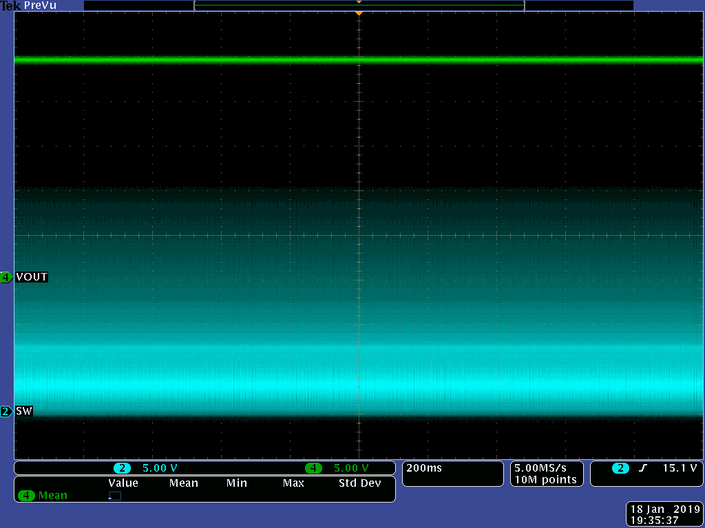
The converter runs without load at normal operation (load are single pulses). When I connect a 680 uF Electrolyt-C at the output, the output begins to oscillate with ca. 4 V / 2 Hz as seen in the KO picture. The oscillating stops when I connect a KO Sonde (13.5 pF / 10 MOhm) at Pin SW of the LM2733. But replacing the KO-Sonde with a ceramic C with 13.3 pF to GND do not help, either not in combination with a 10 MOhm to GND. The oscillation also stop when I connect a piece of wire to pin SW which I hold in my fingers (the 'magic finger effect'...).

  • Hi Michael,

    The phenomenon is quite weird from your description. What's the Vin, Vo value and load current? And could you please share your schematic and layout to help us analyze the issue. Thanks.
  • Hi Zack

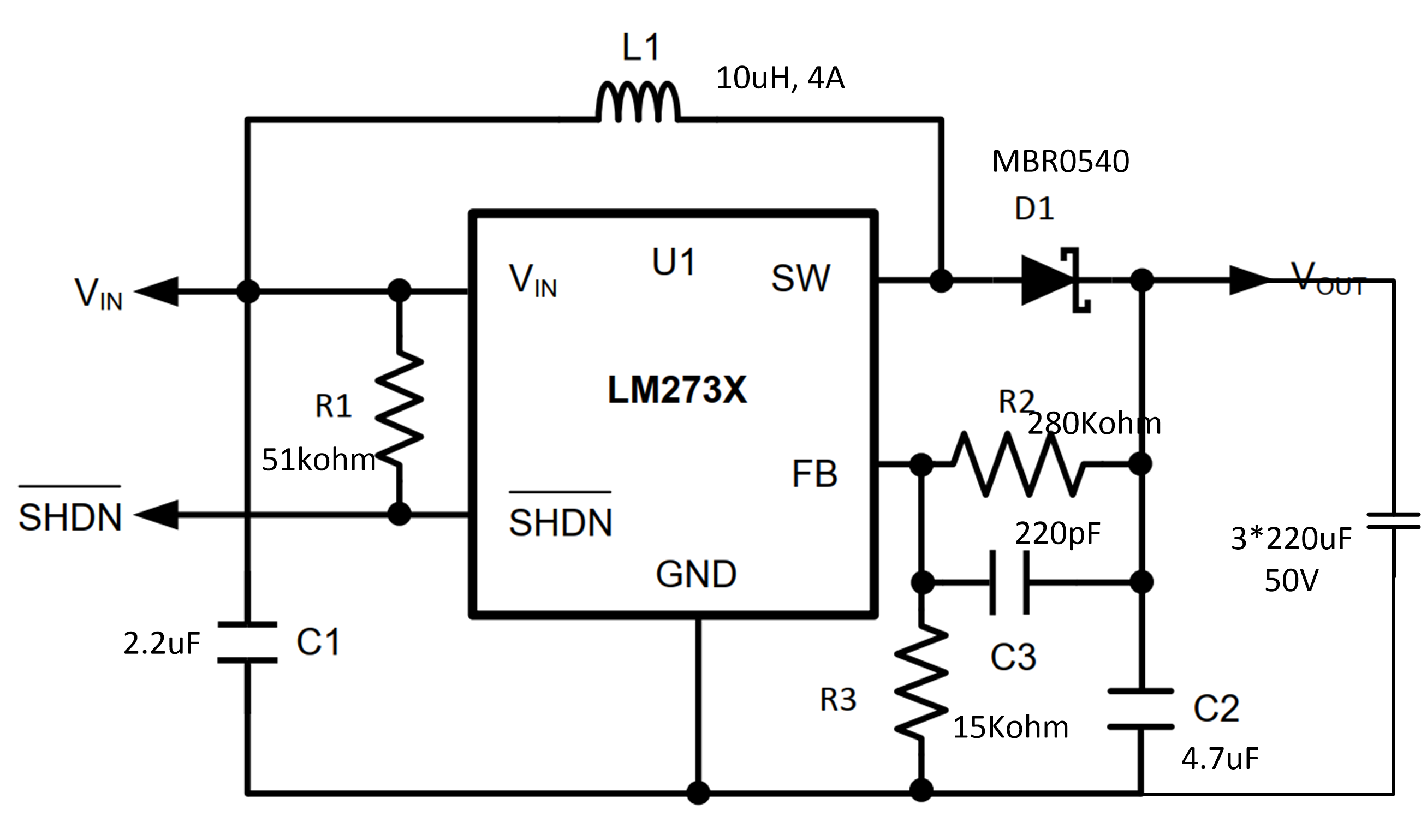
    Excuse me, I thought that the schematic was attached. Her it is:

    It is a hand wired prototype now, but I pay heed to keep wires short and to have a proper GND.

    Vin is 5V, Vout is 28.25 V when running without oscillation (no C 680 uF) or ca. 28..32 V when oscillating with C 680 uF at the output.

  • Hi Michael,

    The picture is not clear to see the component values. Since this is a hand soldered prototype, take care of the GND wire and it's better to use thick GND wire and short power loop. Parasitic trace inductance with cause noise and ringing and may cause this phenomenon. You could refer to part 10 layout in the datasheet to see how to solder wire correctly . Place a 100nF ceramic capacitor close to Vin pin and groud. Solder the feedback components close to FB pin of device.
  • Hi Zack

    I really used wrongly a 2.2nF instead of 2.2 uF-C near the chip. After correcting, the switcher is minimal less sensitive to oscillate, but the problem is still the same. As soon the large 680 uF-C is connected too 'direct', it begins to oscillate. With ca. >30 ohms in serie between switcher output and 680 uF-C it's stable. But the step answer when the 680 uF-C is discharged with a pulse (8A, 300 us) as seen in the KO-plot is very poor: the output overshoot to ca. 33 V instead of the nominal 28V:

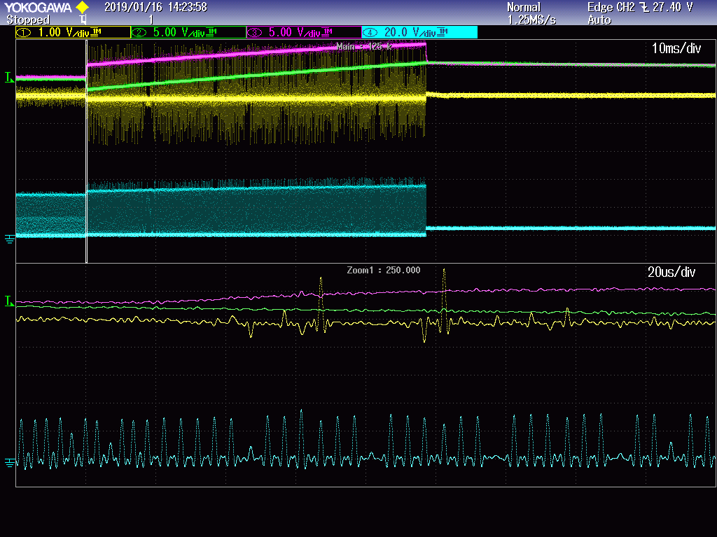
    KO-Plot: CH1 (yellow): Vin, CH2 (green): V on C 680 uF connected over 120 ohms, CH3:Vout of the regulator, CH4: input current (Gain:-1V/A)

    I guess that this large overshoot has the same reason as the general instability with a too lrage output-C.

    Note: I tried to enlarge the Feedback-C from 68 pF to 168 pF: this made the oscillating slower (ca. 1 Hz instead of 2 Hz). I also tried to connect the C 680 uF over a series diode (to avoid reverse current), but the regulatopr still oscillate.

  • Hi Michael,
    1. Please update the schematic again with a clearer version. How do you supply the boost converter? With a power supply or just a battery? What's the current limit of power supply. When oscillation happens, the input voltage also oscillates, so please enlarge the input capacitor values to reduce the amount of voltage ripple. 2.2uF is not enough. The 100nF ceramic close to Vin pin is still necessary even you use a big value input capacitor.
    2. Could you also provide the SW pin waveform when 1 or 2Hz oscillation happens. Thanks.
  • Hi Zack

    Thanks for your help! First, here is a clearer schematic (C 680 uF is connected via a 120 ohm series resistor):

    The capacitors at Vin are as follow: 1 uF + 1 uF + 2.2 nF, all ceramic, direct at the chip. At the 5V-input is an additional power reservoir with 220 uF. The 5V is supplied with a linear laboratory supply with 3 A current limit.

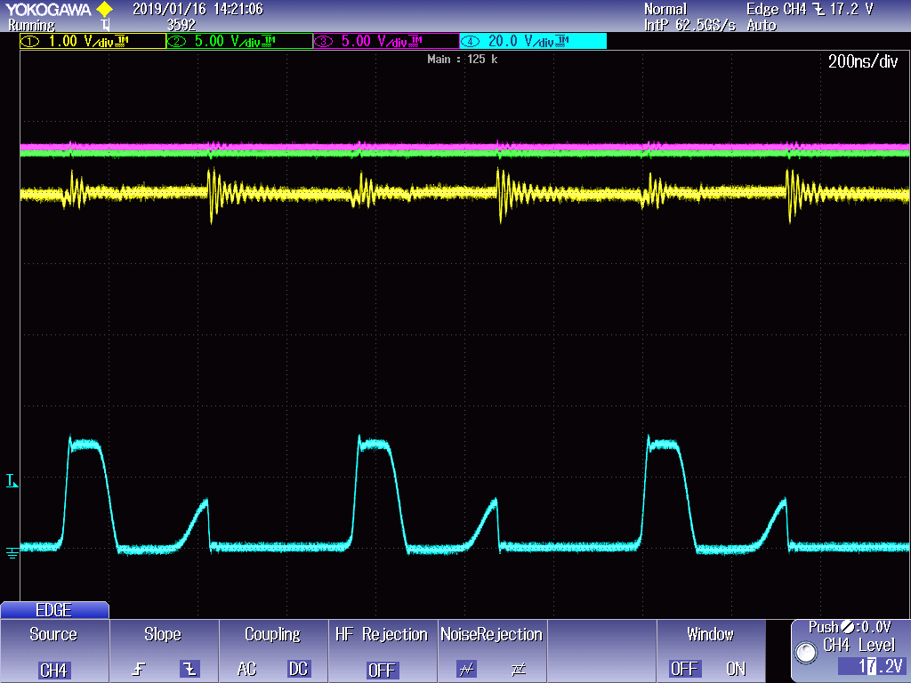
    Here a waveform of the continuous, not oscillating state: (Ch1: Vin, Ch2: voltage at 680 uF-C, Ch3: Voltage at converter out on C 10 uF, Ch4: LM2733.Pin SW):

     fffff

    And here the step answer when the C 680 uF is discharged with a pulse (4A, 300 us):

     ff

    The requested waveform at Pin SW when the regulator is oscillating can I not deliver because the oscillation stops when the Scope-Probe is connected at Pin SW. But I expect that it will be than the same situation as in the Plot above when the regulator is stimulated by a discharging pulse at the output.

    Regards Michael

  • Hi Michael,

    First please select a larger current rating inductor because device current limit is 1.5A typical and 1A minimum.
    The picture you shown here is very strange. After discharged with a pulse, the Vout increased to a higher value? 32v? Will it drop to nominal 28V after several hundreds of milliseconds?
    What will help if you remove the 120ohm resistor?
  • Hi Zack
    1) I choose this inductor, because the switcher runs 99.9 % of the time in idle state with a few mA current consumption. There is for sure no thermal problem on the inductor, and the saturation current is min. 1.4 A - is there another reason to change?
    2) The output of the switcher (magenta signal, Ch3) rise to ca. 34V when the C 680 uF is following over a 120 ohm reistor. The voltage over the C 680 uF follows to ca. 32 V when the switcher finally decide to stop switching. The output voltage sinks after the overshoot back to the nominal voltage of ca. 28.2 V (switcher is not running, C 680 uF is discharged over a resistor), that's right.
    3) I do not clearly understand your last question, sorry. When I remove the 120 ohm resistor (or make it <30 ohms, or replace with a diode), the switcher oscillate what is the initial problem.
  • Hi Michael,

    Thanks for answering it. I'll test your circuit with a EVM today. Reply may be late because we also need to answer other engineer's questions.
  • Hi Michael,

    1. The reason is even though most time the inductor current is very small, when 4A,300us discharge happens, both Vout, Vin voltage drop and input current average increase to over 600mA. The schematic shows the saturation current is 700mA. If it is a 1.4A saturation current inductor, then don't worry about it.

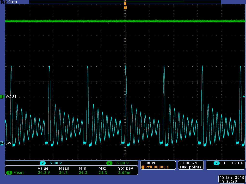
    2. Below is my test schematic waveform using LM2733EVM, Vin is 5V, power supply current limit is 1A. The Vout is set to 25V and 660uF electrolytic capacitor are connected to Vout. You can see Vout keeps at 25V and there is no oscillation.

    It's better for you to apply for an evm and then do the measurement or draw a PCB by yourself.

  • Hi Zack

    Thanks for your effort to help.Unfortunately, I have the overshoot to ca. 35 V what causes the slow oscillating also when I use the same C_FB as you with 220 pF. I will try the EVM or look for another solution.

    Greetings Michael