This thread has been locked.

If you have a related question, please click the "Ask a related question" button in the top right corner. The newly created question will be automatically linked to this question.

TPS780: reverse current

Part Number: TPS780

Hello,

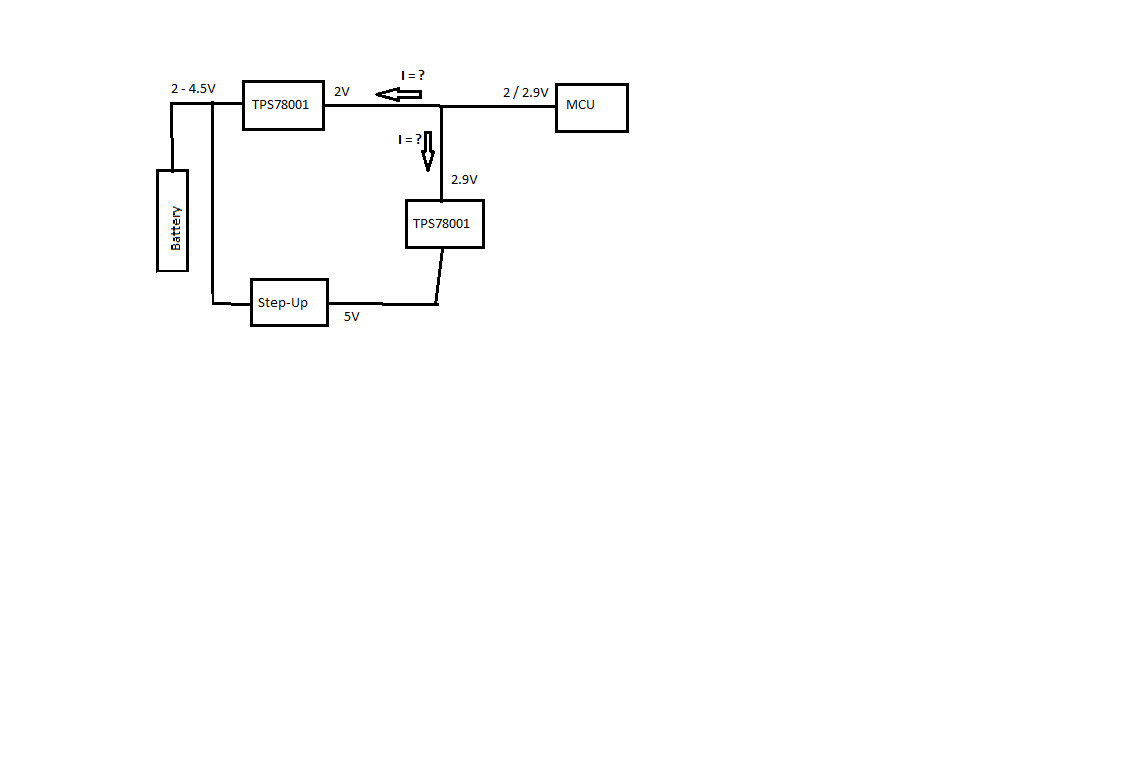
my customer is currently working on a project and he has some questions regarding the TPS78001 (see block diagram below).

His MCU would need to be powered either with 2V or 2.9V depending on which mode the MCU is currently working in and which peripherals (eMMC...) are ON. in other to generated the 2V and 2.9V from the battery (which voltage can vary between 2 - 4.5V) he connected the outputs of the two TPS78001 together (one with a Vout = 2V and the other with Vout = 2.9V). his questions are the following:

1. What will happen with the first LDO (with Vout = 2V ) when its ouput sees the 2.9V voltage coming from the second LDO (back-driving)? how high could the back-driving current be for the first TPS78001?

2. What happens with the second LDO (Vout = 2.9V) when it is disabled, but its output sees 2V coming from the first LDO's (Vout = 2V) output? How big could the back-driving current (reverse current) be in this case. Please see system block diagram below.

regards,

Stani

  • Hi Stani,

    1. When the battery voltage is high, the output of the 2 V LDO can be pulled up to 2.9 V without any problems. However, the Vout pin of the TPS780 has an absolute maximum rating of Vin + 0.3 V. Exceeding this rating could cause permanent damage to the device due to the heat generated by the essentially unlimited back-driving current. If the battery voltage could drop to 2.6 V or lower during this time, this current must be limited with external components.

    For example, an additional diode can be included to protect the device. Mark discusses this in his blog post here:

    2. Assuming the step-up converter is also disabled, the voltage at the node between the step-up and the TPS780 could similarly drop low enough to turn on the body diode of the TPS780 pass FET. This is possible because the capacitors located at that node can discharge through the feedback resistors of the step-up converter. Again, the back-driving current through the LDO would need to be limited externally using diodes or other components.

    Thanks,

    Gerard