This thread has been locked.

If you have a related question, please click the "Ask a related question" button in the top right corner. The newly created question will be automatically linked to this question.

CSD95372BQ5MC: UCD9246 -> CSD95372BQ5MC Interface Logic

Part Number: CSD95372BQ5MC
Other Parts Discussed in Thread: UCD9246, , UCD74120

I need to interface the UCD9246 to the CSD95372BQ5MC.

I don't have the special 'E version of the UCD9246 that has the tri-state PWM function, and it likely isn't an option for this particular project at this time.

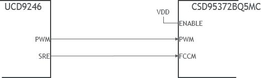
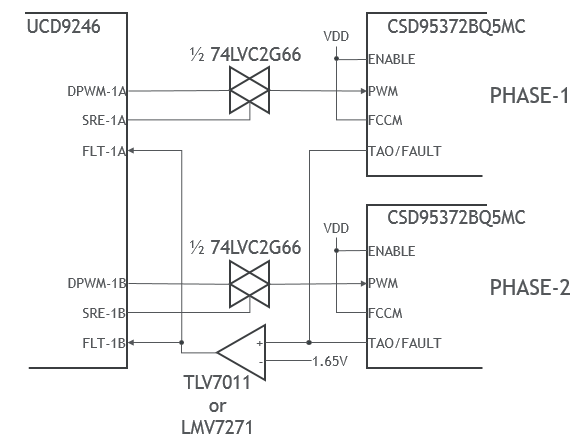
Instead, I need to interface the standard UCD9246 to CSD95372BQ5MC using the PWM and SRE outputs that are available.

The CSD95372B' has a tri-state PWM input, FCCM, and Enable pins.

Please suggest to best way to interconnect the digital outputs of the UCD9246 to the digital inputs of the CSD95372BQ5MC.

We do have an NDA with TI and have the full data sheets at this time.

Thanks, Best, Steve

  • HI Steve,

    As UCD9246 digital output does not have tri-state level, it only have high and level level, that means it can not turn off both high-side and low-side FETs of CSD95372B.

    You need to evaluate if there is problem for your system.

    Thanks
    Qian
  • The UCD9246 has SRE (sync rectifier enable) which I believe can be connected to FCCM of CSD95372. 

    I can also use either a tri-state buffer or a transmission gate enabled by SRE to create the high Z condition at PWM,in of CSD95372.

    For our system we do not have pre-biased output so I don't think we are concerned about the low side FET discharging the output.

    Thoughts?

  • Hi Steve,

    It should be fine to connect UCD9246 SRE to CSD95372B FCCM. It will be good if you keep an option to let FCCM always high.
    I don't have experience on tri-state buffet and transmission gate. Can not comment on that.

    Thanks
    Qian
  • Qian-

    I'm trying to figure out what is wrong with this:

    If SRE = PWM = 0, doesn't that turn off both FETs in CSD95372?  Just like in UCD74120?

    Thanks, Best, Steve

  • Hi Steve,

    When pwm is low and fccm is low, the HS is definitely off, but the LS depends on the status of the zero cross detector. If the inductor current is positive, the LS is on. Otherwise it is off.

    Thanks
    Qian
  • Thanks; I'm pretty sure this is what we want.

    I can't think of a reason this would be bad in our application, a high current, low voltage FPGA rail. We don't need light load or pulse skipping operation. The quiescent current of the FPGA starts at 10A.

    Do you have any further thoughts on this?

    Thanks, Best, Steve

  • After further review, if the LS FET is on, we could have an uncontrolled discharge of the output caps, which is of course bad.

    For a dual phase supply based on the UCD9246, I'm thinking along the lines of the following:

    While this eliminates the possibility for diode mode, we don't need it since we won't have a pre-biased load and we always expect to be in CCM.

    With SRE = 0, the transmission gate will create the high-Z state necessary to turn off both FETs immediately during a shutdown.

    The comparator threshold is set to trip at a relatively high temperature or if a current fault occurs.

    What concerns do you have with this approach?  Would it be better to tie FCCM low and force diode mode instead?

    Thanks, Best, Steve

  • Hi Steve,

    Theoretically your idea should work, but I don't have experience on 74LVC2G66.
    Regarding power stage FCCM pin, either high or low should work. I suggest to use resistor placeholder to keep both options.
    You may need to build a board to test it.

    Thanks
    Qian