This thread has been locked.

If you have a related question, please click the "Ask a related question" button in the top right corner. The newly created question will be automatically linked to this question.

TPS92513HV: EMC Pre-Compliance failure

Part Number: TPS92513HV
Other Parts Discussed in Thread: TPS2378, TPS92513, PMP15004, LMZM23601, TPS92515HV-Q1

Hello everybody,

I have developed a PoE+ constant current source. For the PoE+ PD chip (TPS2378) as well as for the LED driver (TPS92513HV) I chose TI.
With a jumper you can set different currents between 180-700mA.

This works without any problems. The last step was now the EMV pre-compliance, first the wired EN55015... then came the disillusionment.

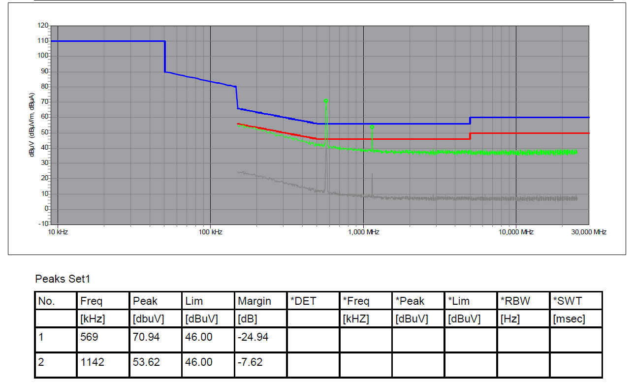
Exactly at the switching frequency of the LED driver (570kHz) a huge deflection as well as at the next harmonic (1140kHz).
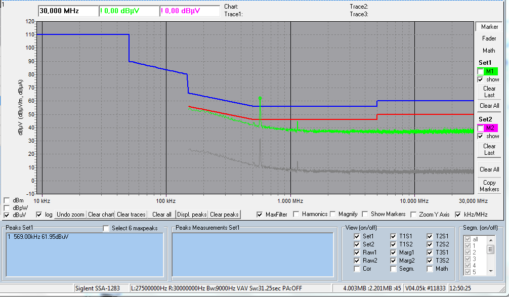
In the appendix you can see the measuring process and the deflections. In the lower frequencies it generally moves very close to the red limit line for the AVG measurement.

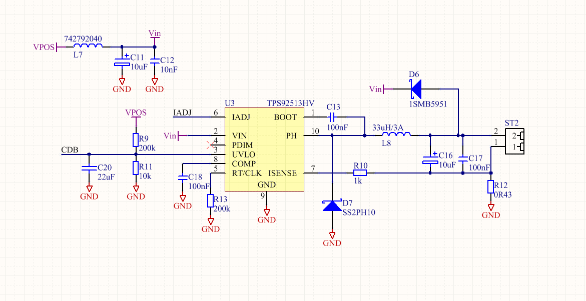
Find attached the schematics and PCB Layout for the LED driver. VPOS is 54VDC and at the output there was a LED with 300mA for the test.

  • Hello,

    Compliance to EMI requires testing the whole system. It seems there is not enough filtering at you lower frequencies, the fundamental and second harmonic. If this is a second stage to an off-line converter the EMI filtering may not be as difficult since it is already pre-filtered with the previous stage. This is all part of EMI filter design, what is L7 in your design?

    Best Regards,
  • Hi Irwin,

    Thanks for the fast reply. The first stage is always a PSE I don´t and for the testing I have use a RIGOL power supply with 54VDC.

    Do you have any suggestion for a filter? L7 ist 742792040 from Würth: 

    Regards,

    Philipp

  • Hello Philipp,

    That is a bead, that won't filter lower frequencies. If there is a power supply in front the whole system needs to be looked at to see what is causing the higher reading at the fundamental and 2nd harmonic. It could be common mode on the output or many other things, this is part of troubleshooting EMI issues.

    Best Regards,
  • Hi Irwin,

    The whole system is the power supply trough a DC LISN to the TPS92513HV for this testing case. 

    The problem is definitely coming from the TPS92513HV.

    There must be any suggestion from TI to filter this chip.

    edit:

    I soldered a LC LP filter in front of the TPS92513HV at VIN with L7 = 1uH and C11 = 10uF.

    This is a cut-off frequency at round about 50kHz. But I have pretty much the same results for the EMI testing.

    Kind Regards

  • Hello,

    EMI is a system level issue. I would first see if your output is coupling back to the input source via common mode. If the filtering of the power source is sufficient the TPS92513 fundamental and 2nd harmonic would not get though the filter. It's a matter of figuring out where the noise is getting back to the input wires.

    Best Regards,
  • Hello,

    I haven’t heard back from you, I’m assuming you were able to resolve your issue.
    If not, just post a reply below (or create a new thread if the thread has locked due to time-out)

    Best Regards,
  • Hi,

    sorry for the late reply but I was out of office last week.

    To be honest the problem is not solved at all. I managed the conducted test with pushing the switching frequency to 2MHz.

    But now I have trouble with the radiated test.

    For other manufacturers of DC/DC or switching converters, a filter is usually recommended. That´s what I miss here.

    Regards

  • Hello,

    A filter may be recommended but if you are driving it with another power supply that is a different problem. Radiated is also a system level issue. What frequencies are you failing? How are the LEDs placed with respect to the board? EMI is not a trivial thing to solve. Just placing a filter on the power supply generally doesn't solve radiated issues, those take time and understanding of where the noise is coming from.

    Best Regards,
  • Please find attached my results. I have stopped the measurement at 10Mhz.

    As you can see the switcher works at roundabout 1,9MHz..

    The LEDs are not placed on the PCB. They are connected externally. 

  • Hello Philipp,

    Again, EMI is a system issue, this will be nearly impossible to solve via e2e. PMP15004 is a TI design That I did that passes Class 3 automotive limits in house, stand alone, which is much more strict than FCC Class B.

    If your LED load is on a wire harness I would look at common mode filtering on the Buck output. Common mode noise can couple back to the input and cause failed test results. There are a lot of possibilities for this showing up on the scan. This is a system being testing with the input power stage included?

    Input EMI Filter Design for Offline Phase-Dimmable LED Power Supplies
    http://www.ti.com/lit/slup298 http://www.ti.com/lit/slup299
    great topic, shows how to design the emi filter, just about everything, simulation and verification

    Understanding and Optimizing Electromagnetic Compatibility in Switchmode Power Supplies
    http://www.ti.com/lit/slup202

    EMI Mitigation Techniques Using the LMZM23601

    www.ti.com/.../pmp15004 The customer should use this as a guide for proper PCB design, layout, etc.

    This TI design showcases a TPS92515HV-Q1 small form factor LED driver optimized to drive two LEDs for a fog light design. The buck topology is implemented as a direct-to-battery, single-stage LED driver which results in a simple and cost-effective lighting solution. Additional design flexibility includes analog and PWM dimming support as well as cycle-by-cycle current limit and integrated thermal shutdown protection. EMI filtering has been included and designed to meet CISPR-25, Class 3 conduction requirements.

    Best Regards,
  • Thank you for this information.

    I will rework the circuit board and give feedback as soon as I'm able to do a new test.

    Kind Regards

  • Hello Philipp,

    I haven’t heard back from you, I’m assuming you were able to resolve your issue.
    If not, just post a reply below (or create a new thread if the thread has locked due to time-out)

    Best Regards,