This thread has been locked.

If you have a related question, please click the "Ask a related question" button in the top right corner. The newly created question will be automatically linked to this question.

BQ24170: Charging 18650 3S using bq24170

Part Number: BQ24170
Other Parts Discussed in Thread: BQ77915, BQ25606, BQ2970, TPS63000, BQ25896, BQ24250

Hi all,

I am new to battery charging and knows little in this field.

I am looking for a solution to charge 3 off the shelf 18650 that comes with protection circuit and is connected in series, using an IC with powerpath capability.

Would bq24170 be fit to use in this solution? Does such solution requires cell balancing in charging?

If not, is there other IC that will be more suitable for such application?

Thank you.

  • Hi CC,

    The BQ24170 can charge 3 cells in series or parallel. For charging 3 series cells, the charger's input voltage must be higher than 12.6V. Cells in parallel auto self balance. Cells in series do not self balance but with the same constant charge current, they each eventually reach the same regulation voltage. The risk for cells in parallel is that when the cell fails to a short, all the cells are shorted. Therefore, we generally recommend adding a battery protector circuit (essentially series FETs) that open and remove the cell from the charging circuit. TI has several battery protection ICs.

    The risk for cells in series is when the cell fails to an open. Even with a protector, the protector creates an open circuit to prevent cell damage and prevents the remaining good cells from charging. There are older separate cell balancing circuits that can be used in conjunction with the protector. TI recently released a device that does both protection and cell balancing for cells in series, the BQ77915.
  • Hi Jeff,

    From the schematic provided in the datasheet, it seems like the battery will share the load and charger on the same line.
    Is there solution that separates them? As this will be a UPS sort of battery for a subsystem in a system, where this subsystem will share the power rail of the main system will the other subsystem. I only need this UPS to power this specific subsystem but not all other subsystems.
  • Hi Jeff,

    In addition to the previous response, do you have suggestion on solution for charging discharging 3P 18650, with the capability of turning the IC off/output, and what is there to look out for in such solution?
    For example like the protector FET circuit you mentioned.

  • Hi CC,

    The BQ24170 has power path select. When input power is applied, that voltage is applied to the system and also to the buck battery charger. The battery is charged per your selected charge current and only provides the system power through the FET driven by /BATDRV if input power is removed. If the input source has enough power for both the system and to charge the battery, this seems like the best solution for your application. Alternatively, we have other chargers like BQ25606 that provide at least a minimum system voltage, bucked down from the input source, at SYS and then internal battery FET from BAT to SYS that allows the battery to charge. The battery only provides the system power if the input source is removed. We have standalone battery chargers without connection to the system as well.

    Regarding protectors, I am not as familiar with those products. From a quick search it appears that the BQ2970 family might work for you. I suggest you submit another e2e post about that family.
  • Hi Jeff,

    Is there a simpler solution to this issue? It is not necessary that bq24710 needs to be used. Sorry for not making the problem clear, I will re state the issue again.

    I am looking for a solution for a subsystem that is powered with voltage rails shared among other subsystems in a system.
    This subsystem will have a UPS module which is either 3S1P 18650 or 3P1S 18650, depending on the complexity of the circuit.
    The solution should separate system power rails from the UPS battery, and preferable the output of the IC can be controlled to switch on or off.

    Thanks for your response.
  • Hi CC,

    So, you just need a battery charger. 3P1S will likely be simpler to charge, depending on the input voltage rail for the charger. What is the input voltage and charge current you need for the 3P1S battery in the UPS module? My only question now is when the UPS is active, how does the battery provide power to the system? I block diagram might help me understand.

    If you need dc/dc converters or a Power management unit (PMU) to provide the system rails, I suggest posting another e2e forum question so that someone from the those forums can help.
  • Hi Jeff,

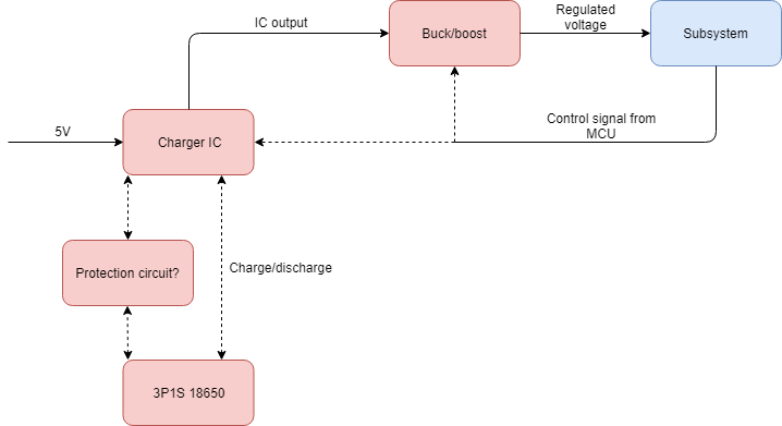
    This is the current architecture that I have in mind. In the incident where the main power from 5V rail is cutoff, the charging circuit will change to supply power to the subsystem by the 18650s.

    When the UPS is active, it will only provide power to the subsystem but not the whole system, so the 5V rail that charges the battery will not be powered.

    The power rails available are 5V and 12V, charge current for the 18650s can be low, around 1A?

    The power consumption of the subsystem will not exceed 10W, so I would like to spec the charger IC to be around 12W.

    The MCU in the subsystem will need to be able to turn off either the regulator, or the charging IC, to differentiate the difference between a normal shutdown of the whole system, or a power issue that causes the 5V rail to be cutoff.

  • Hi CC,

    The BQ25606 is my recommendation for the charging circuit. When powered from 5V, it will provide power to its SYS output (IC output above) with a minimum system voltage of ~3.7V and then starts following the battery voltage up to BATREG. The SYS output always has priority over the BAT output. It has a /CE pin to turn battery charging on and off. Once 5V is removed, the battery at BAT connects to SYS through the internal BATFET and powers the system.

    For the buck/boost, I recommend TI's TPS63000 family. For the protection circuit, I recommend TI's BQ2970 family. For questions on those ICs, please submit new e2e forum posts.
  • Hi Jeff,

    What I am looking for is to turn off SYS output in the circuit, as I am trying to stop the UPS from supplying power to the subsystem when the whole system goes through a proper shutdown process and cutoff the power rail, instead of a power issue that cause the power rail to be cutoff.
    Thank you for your suggestion on the other 2 TI device.
  • Ok. Try BQ24250 which has ENx pins that can be used to put the charger into HiZ which turns off the buck converter and connects BAT to SYS. If you need to also disconnect BAT from SYS (ship mode), I recommend BQ25896 which requires I2C communication for entering HiZ and ship mode.
  • Hi Jeff,

    I have decided to turn off the output through another regulator instead of the charging IC.

    I have came up with a schematic for the whole setup, planning to use NCR18650B for 18650.

    May you check this schematic for the linking up between protection circuit and charging circuit?

    Also there are a few questions:

    - As I am doing a 3P1S with protection circuit suggested above, how shoud the TS pin of BQ25606 be connected?

    - May you explain the use of PMID pin, as I did not understand what the datasheet's RBFET and HSFET meant.

    - As this application did not involve using a USB related function, how should the D+, D- and OTG pin be connected?

    Thank you.

    3P1S protection circuit.pdf

    charging circuit and regulator.pdf

  • Hi CC,

    If TS pin is not used to sense the resistance of a thermistor, you will still need to place a resistor divider from REGN to GND with equal sized resistors in order to trick the charger into thinking the battery is at nominal temperature.

    PMID pin is the input to the buck converter and the output of the RBFET (reverse blocking FET). The RBFET is need to prevent current from flowing from the battery back to VBUS when no power is applied at VBUS. Also, the RBFET used to sense the input current for the input current limit circuit (as set by the ILIM pin resistor).

    If D+/D- is not used, I suggest leaving them floating so that the ILIM pin resistor sets the input current limit. Shorting them sets input current limit to 2.4A.

    If OTG is not used, it must be grounded so that OTG is never enabled.

    When you layout the board, please ensure that C5 and C6 are close to the charger SYS and GND pins.
  • Hi Jeff,

    Thank you for your support.