This thread has been locked.

If you have a related question, please click the "Ask a related question" button in the top right corner. The newly created question will be automatically linked to this question.

ISO5451-Q1: how to limit power supply current? (total dissipated power needs to be below 1.255W)

Expert 6460 points
Part Number: ISO5451-Q1
Other Parts Discussed in Thread: ISO5451

Team,

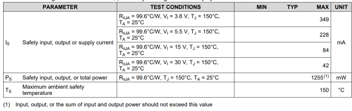
In the ISO5451-Q1 datasheet on chapter: 7.8 Safety Limiting Values, it says that total dissipated power should not exceed 1.255W. Is that because internal isolator structure would suffer? As a resulting question, how to limit power supply current? One way would be to place resistors on power supply pins. But it will cause voltage drop. Is there some better but still simple way to do current limit?

Thanks for your help
TI Customer

  • Hello,

    The specification is given to show the limitation of power dissipation such that the junction temperature of the device does not go beyond 150C. Automotive Q1 grade devices are qualified up to 150C, but higher junction temperature would limit the device's lifetime. During normal operation, the IC will not reach that level of power dissipation, so it is not necessary to add a limiting resistor. You can find the typical supply current graphs in Figures 16 through 20.

    Regards,
    Audrey
  • ...."During normal operation, the IC will not reach that level of power dissipation".... Yes, this is correct but what if some malfunction occurred and temperature junctions exceed 150°C? In that case insulation barrier will be melted! So, some current limiter must be placed on power supply and also on the all inputs and outputs. On the input/output (signal) resistor is enough but power supply is tricky due to voltage drop.
  • Hello,

    I understand your concerns. Please take a look at our whitepaper on "Understanding failure modes in isolators". TI's series capacitive isolation is reinforced, and thus when a failure occurs you will still be left with basic isolation.

    Thank you,

    Audrey

  • Your comment "TI's series capacitive isolation is reinforced, and thus when a failure occurs you will still be left with basic isolation" implies that a user need not worry about a failure because basic isolation remains intact.

    In other words, the mA and mW numbers Section 7.8 of the ISO5451 datasheet can be exceeded, because worst case basic isolation is intact. This is your meaning?

    7.8 Safety Limiting Values

    Safety limiting intends to minimize potential damage to the isolation barrier upon failure of input or output circuitry. A failure of the I/O can allow low resistance to ground or the supply and, without current limiting, dissipate sufficient power to overheat the die and damage the isolation barrier, potentially leading to secondary system failures

  • Hello Doug,

    The Safety Limiting Factors are recommended values to prevent an excess of junction temperature, which is 150C, but the end-application may not exactly match the test conditions which are specified in this table. This is all to say that this table serves as a guideline, but may not match the application in which the customer needs to limit current to prevent excess of 150C junction temperature.

    With regards to actual implementation, a resistor may be placed at the supply pin as suggested before, but I also imagine there is current limiting done at the isolated supply itself, whether by resistor, e-fuse or other method. Aside from short circuit current limiting, the current can also be controlled by the application conditions, which is dependent on the switching frequency and the gate charge (Idd=fsw*Qg).

    Regards,
    Audrey