This is regarding TI part “TPS54061-Q1” for automotive application.
We got the Proto-board with this DC-DC converter mounted.
Design specifications
Typical Input Voltage: 24V
Typical Output Voltage: 12V
Typical Load @ 12V: 10-15 mA
DC-DC converter switching Frequency set: Approx 560Khz
During output ripple measurement we have observed the below issue.
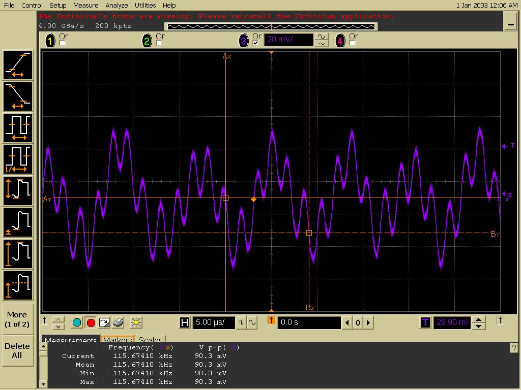
1. @24V input the output ripple amplitude is approx 90mV. Should be less then 50 mV
2. The output ripple frequency is approx 115Khz, should be close to DC-DC converter switching frequency.
3. as per attached figure (@24V input), output ripple has two frequency components, The switching frequency(560Khz) is superimposed on lower frequency(115Khz) components.
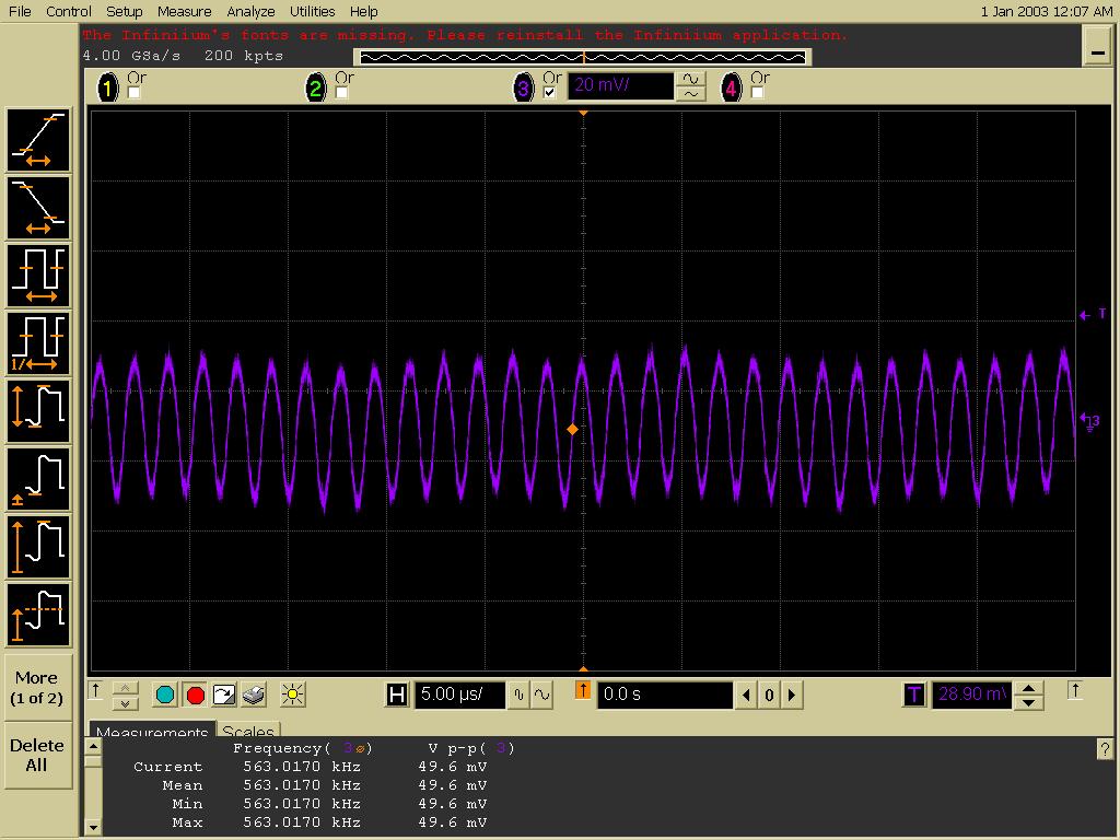
4. If we increase the input applied voltage to 30V, the output ripple amplitude is approx 50mV and ripple frequency more then 563Khz.
Please comment on above issue.
Below is the description of design and measurements
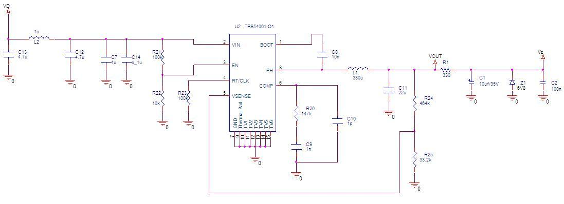
We are using TPS54061-Q1 DC-DC convertor for converting 24V to 12V followed by zener diode as voltage regulator for Vz=6.8V as shown below:
|
|
Issue: If we increase the input voltage, the output ripple will get reduce and waveform get smooth as shown below . Why?
Below are the measured ripple with different input voltage
|
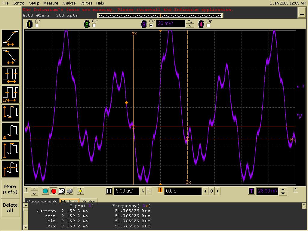
Figure 5 Ripple with input 18V Vp-p = 160mv , freq=51KHz |
|
Figure 6 Ripple with input 24V Vp-p = 90mv , freq=115KHz |
|
Figure 7 Ripple with input 30V Vp-p = 50mv , freq=563KHz |
|
Figure 8 Ripple with input 38V Vp-p = 70mv , freq=283KHz
|

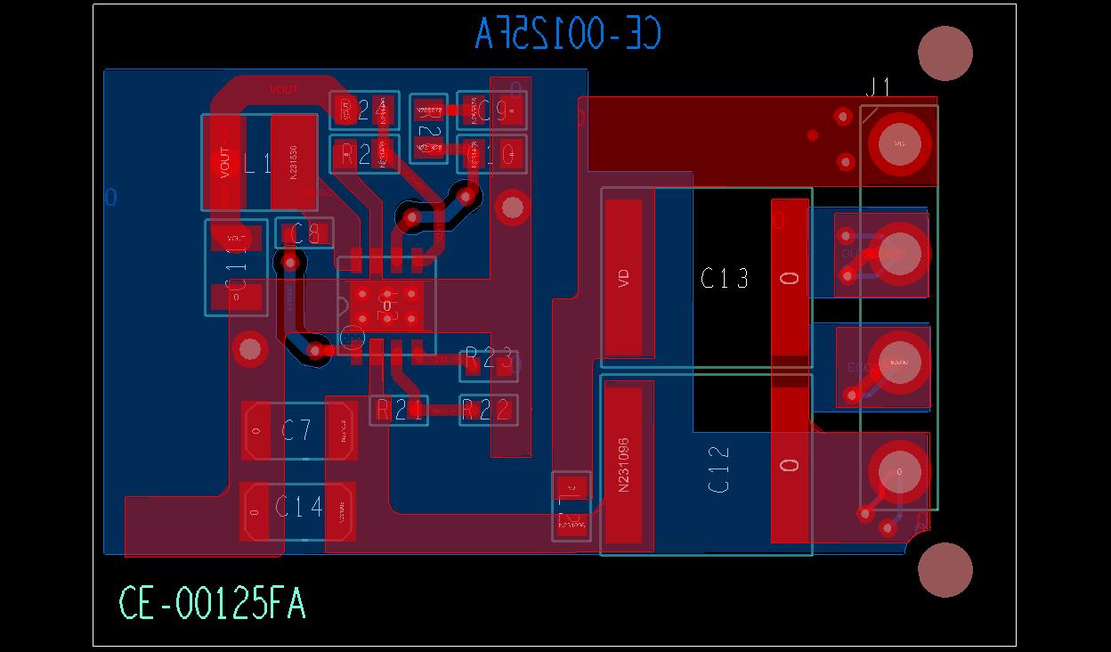
Refer below figure for Layout of design :
Layer in Red is TOP layer and Blue is Bottom layer