This thread has been locked.

If you have a related question, please click the "Ask a related question" button in the top right corner. The newly created question will be automatically linked to this question.

LM5041: LM5041 Synchronous rectification

Part Number: LM5041
Other Parts Discussed in Thread: LM5026, LM5036, LM5033, UCC2897A

Hi,

I am planning to design a circuit using LM5041 reference design.

My specification is  same as the LM5041 evalkit spec. That is Vin=35V to 80V, Vo=2.5V/50A .

I have some doubt regarding LM5041 Evaluation board synchronous rectification. My doubt is

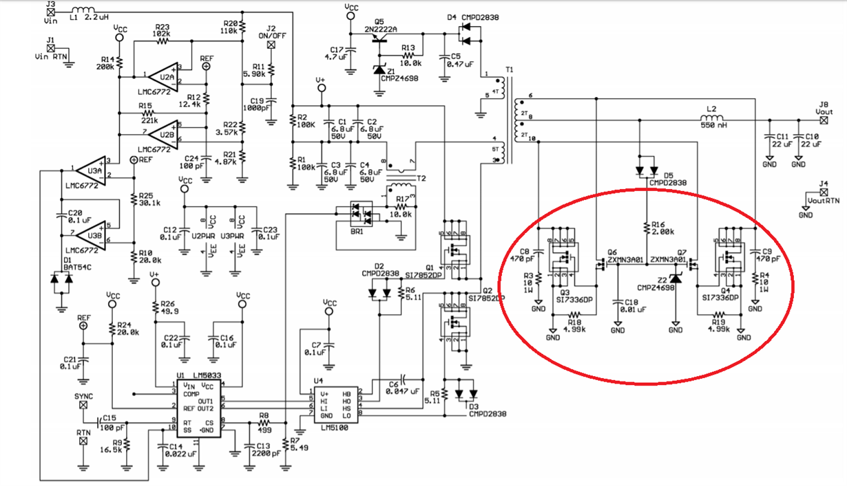
1. Can i implement a self synchronous rectification circuit in my design by removing T3 and T4 driving transformer and its driver mosfets?. I am planning to implement a self synchronous circuit  as in LM5026 evaluation board. Will this solution work out?

2. Up to what output current and voltage we can use  self synchronous circuit?. What is its design criteria ? or is it related to topology ?. Is there any efficiency problem?

Regards

Aneesh

  • Hi Aneesh,

    TI have an new half bridge controller, LM5036, which can cover this application at a lower power stage cost that the LM5041.

    The LM5036 also includes SR drive signals, because one of the challenges with lower voltage output design and self driven synchronous rectifiers is that the voltage from the transfomer winding is too low to fully enhance the mosfets and hence the Rds-on is higher and power dissipation increases.

    www.ti.com/.../universalsearch.tsp

    You can do a design on webench for a 3.3V 80A out using the LM5036, I have requested that the webench tool be update to allow lower voltage designs.

    The LM5036 webpage also includes a design calculator to help with the design.

    Regards

    Peter
  • Dear Peter,

    we already started the design with LM5041. We are not in a position to change the controller in this stage.

    Could you please tell me the impact of replacing the Synchronous rectification driver with the self one? kindly answer me the following two doubts

    1. Can i implement a self synchronous rectification circuit in my design by removing T3 and T4 driving transformer and its driver mosfets?. I am planning to implement a self synchronous circuit as in LM5026 evaluation board. Will this solution work out?

    2. Up to what output current and voltage we can use self synchronous circuit?. What is its design criteria ? or is it related to topology ?. Is there any efficiency problem?

    Regards
    Aneesh
  • Hi Aneesh,

    You cannot use self driven SR's with a push pull. The problem is there is no gate drive voltage available during the free wheeling period on the secondary side and the power stage will rely on the body diodes of the SR's to rectify the voltage and carry the load current.

    One the forward the converter self driven SR's work well at 5V but you will struggle to full enhance Mosfets in a 3.3V design due to the lower gate drive voltage. At 12V you need to take care that the voltage on the gate is well controlled and does not overstress the gate. There is a need for some RC timing delays but generally the circuits works well in forwards.

    Regards

    Peter
  • Dear peter,

    Thanks for your feedback. I have some more query.

    what are the typologies in which self driven synchronous rectification can be used and cannot be used?

    Regards
    Aneesh
  • Hi Aneesh,

    The active clamp forward is the only topology I know where you can get the correct SR drive signals for the transformer.

    You can get the turn-on signal for the Flyback if you put the SR in the return leg from the opposite terminal of the transformer but you need some additional circuitry to command the turn-off especially if the flyback is in Continuous conduction mode.

    Regards

    Peter
  • Hello peter,

    Thanks for your feedback.

    LM5033 Evaluation board is made with Half bridge Topology in which TI is using Self synchronous rectification. Kindly find the attachment below.

    Is this means in other topologies apart from Active clamp forward also  Self synchronous rectification can be used?

    Kindly give me some clarity on this topic.

    Regards

    Aneesh

  • Hi Aneesh,

    This is not an optimal solution the body diodes of the SR's must conduct the current during the off time of the primary side fets.So at high line input voltages the duty cycle on the primary will be relatively short and the body diode conduction period on the SR's will be longest. The high VF of the body diode and higher reverse recover loss may negate any benefit of the SR's compared to schottky devices.

    Regards

    Peter

  • Hello peter,

    You are right . I understood your point. one more doubt i have........

    Synchronous drive for active clamp forward (ACF) and single switch forward will be same right?

    I mean Self synchronous rectification can be implemented in single switch forward also right?. You have mentioned it only for ACF.

    Regards
    Aneesh
  • Hi Anessh,

    Yes self driven SR's will work in ACFwd and single switch forward. If your goal is higher efficiency with ACFwd is a better choice over standard forward topology.

    See UCC2897a EVM, www.ti.com/.../sluu357.pdf

    Regards

    Peter
  • Hello peter,

    Thanks ...................

    Regards
    Aneesh