This thread has been locked.

If you have a related question, please click the "Ask a related question" button in the top right corner. The newly created question will be automatically linked to this question.

TPS92512HV: Set PDIM pulse to nearly 95% duty cycle, and something blew up on the board

Part Number: TPS92512HV

Previously was pulsing LEDs for 1200us ON-time every 120Hz, with no issue (PWM duty cycle = ~14.4%).  Tutring duty cycle up to 95% resulted in either TPS92512HV or catch diode blowing up on board.  Output pins of IC now measures a short to ground.  

  • Hello Brian,

    It should be able to run 100% duty cycle provided the part can thermally (heatsinking) handle your operating conditions. What is you input voltage, output voltage and LED current? What is your catch diode part number? Any other relevant information.

    Best Regards,
  • Vin = 48V
    Vout = 38.1V (12 LEDs in series, Vf = 3.15V + 300mV Vsense)
    LED Current = 2A
    Four vias attached to ground pad connected pad to ground plane
  • Hello Brian,

    What is the freewheel diode part number? duty cycle will be high, how long before the buck converter fails after turn-on? If it is long enough for it to heat up can you check the IC temperature?  What is your switching frequency?

    Best Regards,

  • Diode Part Number is Diodes, Inc B360A-13-F. Failure occurred almost 1 second after turn-on. LEDs were on, and then about 1 second later there was a snap and they were off. Board will not power anymore. No visible damage to board. All LEDs illuminate using diode setting on multimeter so LEDs are not damaged. Short measured from IC pin 10 (PH) to GND.

    Switching Frequency = 700 kHz

  • Hello Brian,

    Seems one second wouldn't be enough for the IC to thermally run away however if the inductor starts saturating: From a previous comment, you're using IHLP inductors. Can you look at the inductor current waveform? It's partially in saturation at 2.25A. Or try an inductor with higher saturation current.

    Best Regards,
  • Hello Brian,

    I haven’t heard back from you, I’m assuming you were able to resolve your issue.
    If not, just post a reply below (or create a new thread if the thread has locked due to time-out)

    Best Regards,
  • I would like to keep this issue open while I procure replacement material in order to test the board out.
  • Hi Brian,

    I haven’t heard back from you, I’m assuming you were able to resolve your issue.
    If not, just post a reply below (or create a new thread if the thread has locked due to time-out)

    Best Regards,
  • I would like to keep this opened as I am still trying to finalize my design
  • Hi Irwin,


    If I am seeing 400mVpp of ripple across Rsense (0.15 ohms), then am I to assume my inductor ripple current is 2.67A? The LED current and the capacitor current all flow through Rsense, so if I am seeing 400mVpp swing about 300mVDC, wouldn't my inductor ripple current equal 2.67App?
  • Hello,

    You have to make sure that is a real measurement. They way to tell is to zoom in and see if it is a triangle/sawtooth waveform. The noise spikes don't count and can be caused by many things such as diode recovery, diode capacitance, MOSFET capacitance, Inductor winding capacitance, noise picked up by the scope probe (check by measuring the GND your probe ground is tied to), etc. Low level signals are sometimes difficult to get accurate so don't always believe what you see on the oscilloscope, verify it.

    I forgot to add, when I am troubleshooting a lot of times I'll lower the current set-point way down to prevent damage until I know things are working correct.

    Best Regards,

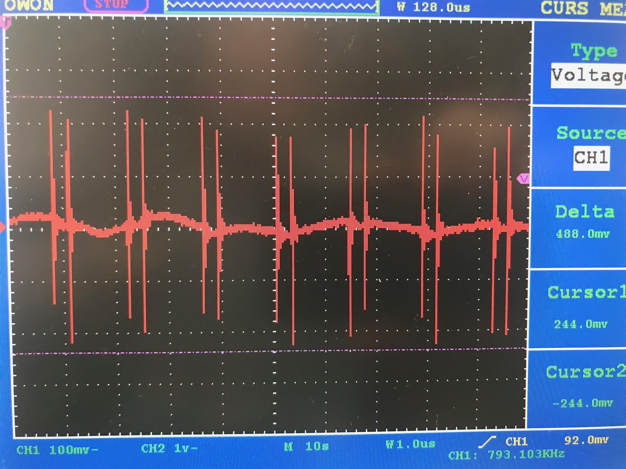
  • I measured The Ground node with respect to an adjacent ground node, using a scope probe and a very short ground, such as a spring probe.  The waveform is NOT a sawtooth.  The noise is the same frequency as Fsw, 700kHz.  See attached.

    My board is a two layer FR4 PCB.  All components on the primary side.  

  • Hello Brian,

    There are two things going on there. Zoom into the noise spikes to see what that looks like. Since this is a closed loop design that noise should be fairly small to integrate out. Layout issues, inductive loops in the switching and recirculating loop can cause excess noise such as this. I can see the triangular waveform however it seems to be changing which isn't right. If Vin and Vout are stable the slope should not be changing. It's also possible there is a resonance getting excited by the switching.

    Best Regards,
  • This noise disappears during the PDIM off time

    My Vin is stable until the PDIM on time, in which I experience 5-6Vpp of ripple.  I have 12 LEDs in a 3x4 grid, so a loop is unavoidable.  I am currently on a 2 layer FR4 board, but will be moving to a 4-layer FR4 board.

  • Hello Brian,

    The oscilloscope picture above is not 5-6 Vpkpk of ripple. The actual ripple looks to be less than 0.5 Vpkpk. A ceramic capacitor near the output of the inductor to GND should eliminate the noise spikes. You have to figure out what you are measuring. Zoom in and see what the noise spike frequency is. Also, looking at the ripple and inconsistency I would make sure there is no test set-up issue with ground loops. Also, is the IC ground reference solid for the IC including the components that go to the IC? Is it routed so the the power path doesn't cause issues with the components going to the IC?

    Best Regards,
  • The scope capture above is the GND node measured with respect to a nearby GND node using a spring ground probe. That appears to be noise in my GND net.

    The noise I experience on my input voltage line is not captured here, I was sharing it wrt your comment about Vin and Vout being stable or not.
  • Hi Brian,

    I haven’t heard back from you, I’m assuming you were able to resolve your issue.
    If not, just post a reply below (or create a new thread if the thread has locked due to time-out)

    Best Regards,
  • Hi Irwin,

    I was waiting to hear a response from you.  The picture I last sent was my ground node measured with respect to another adjacent ground node using a short spring ground.  This, to me, shows that I have a tremendous amount of noise in my ground plane when I am pulsing the LEDs.

    Do you agree?

  • Hello Brian,

    Sorry, didn't realize you were waiting for a response. If that is a true measurement you will have to look at the layout to figure out if this is affecting operation. If that signal is real (not something picked up in the probe loop or other test equipment interfering with measurements) it doesn't look good. Current sense is a low level signal as well as other signals going to this IC. Your layout should have a solid ground at the IC and no current flowing through ground that components that are referenced to the control pins of the IC. It may be best to lower the current way down to see if the circuit is operating correct or get hold of the EVM to try it out.

    Best Regards,
  • I'd like to reiterate - the noise seen above is at my switching frequency (700 kHz, the larger time gap between spikes corresponds to my duty cycle Vo/Vin = 38.1/48, and the narrow time between spikes is 1-D). This noise disappears during the PDIM off time or when I disable the LED operation entirely.

    The LED current path runs on the top of my PCB, with a ground plane on the bottom side (2 layer PCB), but I have very large ground voids underneath my LEDs. Could this be the mechanism that noise is coupling into my ground plane during LED operation?
  • Hi Irwin,

    I am looking at the EVM schematic. They spec out Vin = 48V, Vout = 5-25V, L = 33uH, and Fsw = 570kHz. These numbers do not jive with the datasheet. The datasheet says to calculate an inductance using the equation 18 with the lowest Vin and the highest Vout and an Iripple of 75mA. Using the Vin and Vout above, and 570kHz and Iripple = 75mA, I calculate a 280uH inductor, while the EVM uses a 33uH inductor. A 33uH inductor in this case should yield a ripple current of 637mA.

    This is very confusing. The datasheet says to target Iripple = 75mA, the EVM should have a Iripple of 637mA, and the example application in the datasheet has an Iripple of 89mA (Equation 34)

    I am very very confused as to what kind of ripple current I should be targeting in order to size the inductor to my application, because right now I am struggling to fit a 100uH inductor into my design based on Vout = 38.1V and a Fsw of 700kHz.  Since I want to run 2A through my LEDs, a 100uH is looking to become very large when saturation ratings come into play.  

  • Hello Brian,

    Before I go further, what measurement ground to adjacent ground? Is it even relevant to the IC, what are you measuring? Voids in the ground plane are fine if the don't affect the circuit operation. If there is an output capacitor across the LEDs and it's located correct the LED layout shouldn't be too critical since it will be seeing mostly DC current.

    I would recommend testing this with the EVM so you can eliminate your layout as the issue. You could also lower the LED current down significantly to prevent damage to see if it is operating correct.

    I'm not sure what the switching frequency duty cycle has to do with this issue. If the PWM is off I would expect the switching noise to go away, if it is on I would expect to see some indication of switching (noise spikes that probably aren't real due to measurement), the other noise can be a problem depending on where it is in the ground path.

    Best Regards,
  • My Rsense is connected to ground through a via. That measurement was taken on the Rsense pad connected to ground, with the ground lead of the scope probe connected to the via. The ground via is located approximately 4mm away from the Rsense pad.

    I don't have the ability to test against the EVM since we have a compliance deadline in one month. I need to get to the bottom of this now.

    I only mentioned the switching frequency because I wanted to demonstrate that the noise is behaves very similarly to the switching characteristics of the regulator, and is not something stray getting picked up by the scope.

    I am very interested in understanding why the datasheet would recommend me to target 75mA of Iripple while the EVM does not.
  • Hello Brian,

    Please re-read that, it does not state target Iripple = 75 mA; "The peak inductor current is
    used in current mode control and to maintain a good signal to noise ratio it is recommended that the peak-topeak
    ripple current (IR Equation 18) is greater than 75 mA for dependable operation. This allows the control
    system to have an adequate current signal even at the lowest input voltage.". It states there should be at least 75 mA of ripple to operate correct. The calculations are guidelines. I calculated the ripple to be 0.6A at 48V input and 25V output, this is 40% ripple which is reasonable. A design depends on what the end application is, if it needs to be very small the switching frequency will be high as well as the ripple to keep the inductor small. Design choices are compromises to what your design needs to do, does it need to be small? does it need to be efficient? does it need to be inexpensive? You can have two designs that drive 2A that are completely different. If you don't need the low ripple current you should decrease your inductor value.

    You should probably just try using the EVM to see if it is close to what you want to do.

    Best Regards,
  • Hello Brian,

    I'm not sure I believe the oscilloscope signal, if there's that much noise on 4 mm of trace something isn't right. How wide is the Rcs trace? What copper weight is the board? What size is the via hole?

    I assume you understand that the switching of the converter creates di/dt which also creates dB/dt that the oscilloscope picks up via the probe/probe loop? The probe isn't going to pick up random noise but the noise created by the LED driver or any other high dv/dt, di/dt signals near the measurement.

    The datasheet does not recommend that, it just states that you want the target current ripple to be higher than 75 mA due to how the current sense in the IC works. Please re-read that section.

    Best Regards,
  • Hello Brian,

    This has been taken off of e2e for direct help.

    Best Regards,