This thread has been locked.

If you have a related question, please click the "Ask a related question" button in the top right corner. The newly created question will be automatically linked to this question.

TPS23753AEVM-001: How to troubleshoot a not working design/PCB?

Part Number: TPS23753AEVM-001

Hi,

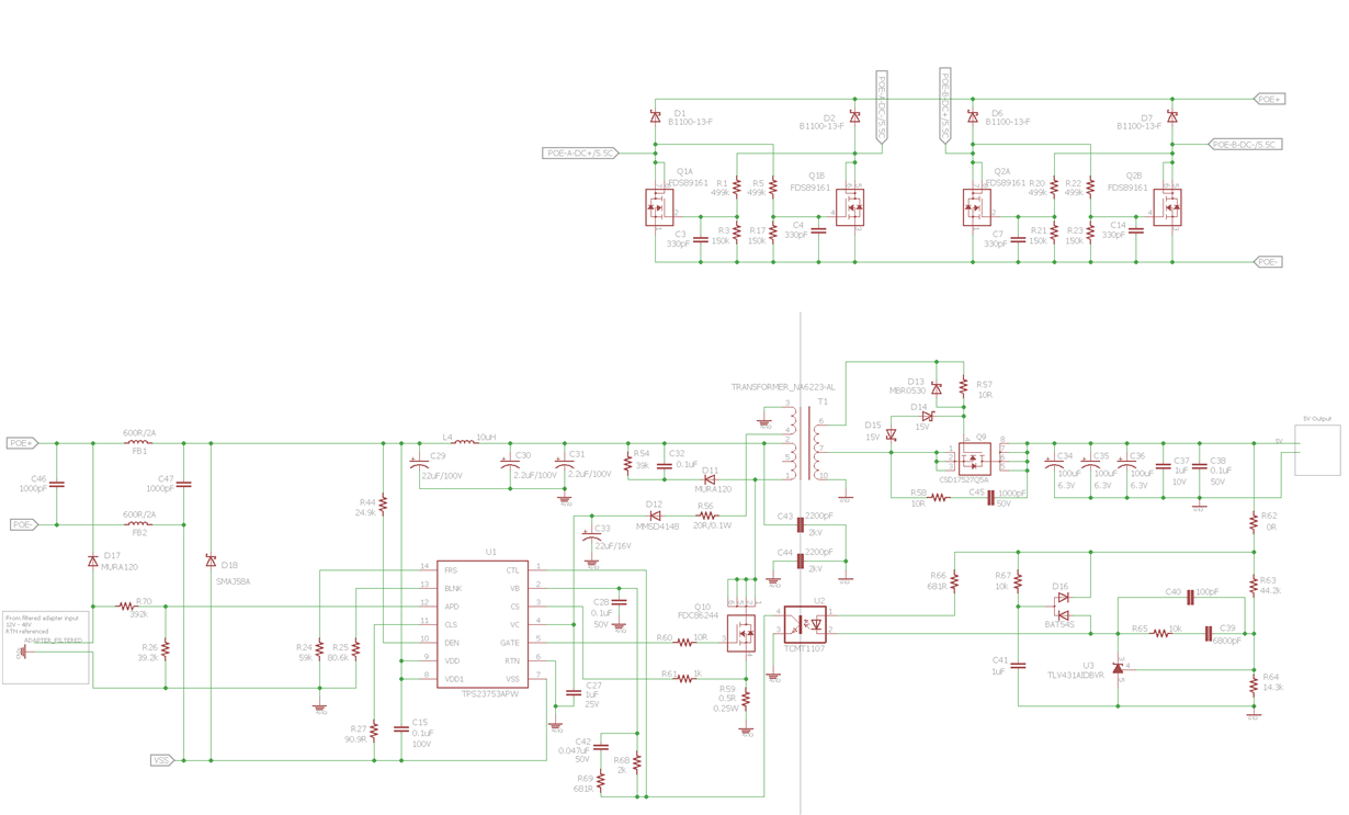
We have been trying to re-create a PoE board based on schematics of the EVM board, the redrawn schematic is attached. So far, the problem with two prototype PCB are: when an external adapter is connected, the primary switch MOSFET Q10 becomes hot quickly, and there are not positive voltage output at supposedly 5V output. 

I have gone through the schematics and compared it with the one in EVM user manual several times, so far I don't identify any issue.So schematic is less likely a source of problem. Other possible sources are component packages, wrong components etc. 

How do I go from here to troubleshoot?

Many thanks in advance.

Zhiyong

  • Hi Zhiyong,

    Does the converter work properly with a PSE attached to the RJ45 input? Are you attempting this with low Vin (12V-24V) on the adapter? Is this occuring with 48V at the adapter? 

    In any case, how much output load does it take for this to occur? What does Vout look like when this occurs?


    Thanks,
    Tom Amlee
    PoE PD Apps Engineer

  • Hi Zhiyong,

    Are you still working the issue or have you found resolution? Let me know. If continued support is needed, please respond to the questions I posted, above.

    Additionally, which EVM are you following? The transformer appears to be from TPS23753AEVM-235, which is not a Wide Vin design.

    Thanks,
    Tom Amlee
    PoE PD Apps Engineer