


Hi everybody from Italy
As you can see in the linked messages -I'm tryng to drive a Cree COB led with the TI LM3404.
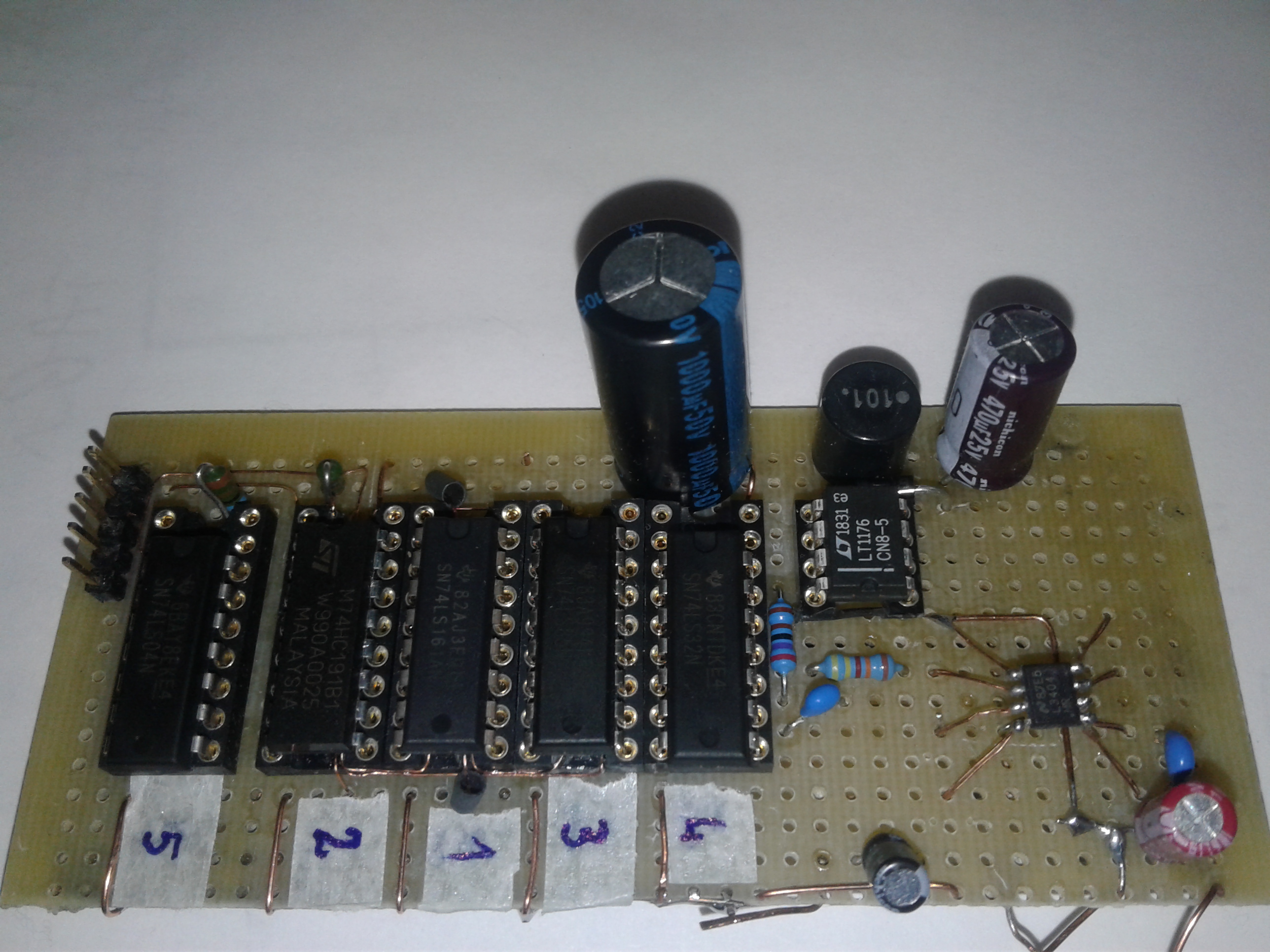
At the beginning I received help from Mr. Irvin and - thanks to this - I was able to realize an excel spreadsheet and afterwards a pr ototype which you can see down here
The schematics were realized according to the one in the LM3404 datasheet page 23.
The components were chosen basing on the following calculations as in the pages 24, 25 and 26 of the same datasheet:
| Input voltage: | 24 | Vin [Volt] | 1,34E-10 | cost | |||
| LED forward voltage: | 17,5 | V0 [Volt] | 0,4 | inductor ripple curront increase | |||
| LED current: | 0,65 | IL [Amp] | 0,1 | ΔiF | |||
| Switching frequency: | 3,00E+05 | Fsw [Hz] | 2,25 | rD | |||
| RON =V0/(1.34 E-10*Fsw) | 440298,5075 | RON [Amp] | 442000 | Ron comm | |||
| fSW =V0/1.34E-10*RON | 298845,1408 | Fsw comm [Hz] | |||||
| tON = 1.34E-10*(RON/VIN) | 2,46783E-06 | ton [sec] | |||||
| ΔiL = 0.4 *If | 0,26 | ΔiL [Amp] | |||||
| LMIN = ((VIN - VO)*tON)/ΔiL | 6,35942E-05 |
|
6,20E-05 | H L comm | |||
| ΔiL= ((VIN - VO)*tON)/Ltip | 0,266685215 | [Amp] | 6,10E-05 | H L comm | |||
| ΔiL= ((VIN - VO)*tON)/LMax | 2,71E-01 | [Amp] | 6,30E-05 | H L comm | |||
| ΔiL= ((VIN - VO)*tON)/LMin | 2,62E-01 | [Amp] | |||||
| IL(peak)=IL+0,5*ΔiLMax | 7,86E-01 | [Amp] | |||||
| ΔiL(led short)= ((VIN - 0,2)*tON)/LMin | 9,47E-01 | [Amp] | |||||
| IL(peak )=IL+0,5*ΔiLMax | 7,86E-01 | ||||||
| Rsns=(0,2*L)/((If*L)+(V0*tsns)-(((Vin-V0)/2))*ton) | 0,345146642 | ohm | 0,3 | ohm | |||
| Zc=(ΔiF*rD)/(ΔiL-ΔiF) | 1,349849775 | ohm | |||||
| C0=1/(2*PI*Zc*fSW) | 3,95E-07 | F | 0,33 | uF | |||
| D=tON/(tON+toff-min) | 0,891611971 | ||||||
| if=0,2/(Rsns-((Vf+0,2)*tsns)/(C0+(ΔiL typ/2))) | 0,666685343 | ||||||
| Id=if*D | 0,594424633 | ||||||
| Pd=0,3*Id | 0,17832739 |
The other integrated circuits that you can see realize a PWM dimming controller and other functions.
The Item is perfect and now a new lamp it is hanging from my lab ceiling.
The only problem that sticks to my mind is that - despite the expected current was 650 mA - the real measured current is 480 mA as you can see in the multimeter down here.

So I realized another prototype by changing the starting data as you can see in the next spreadsheet.
| Input voltage: | 24 | Vin [Volt] | 1,34E-10 | ||
| LED forward voltage: | 17,5 | V0 [Volt] | 0,4 | ||
| LED current: | 0,8 | IL [Amp] | 0,1 | ||
| Switching frequency: | 3,00E+05 | Fsw [Hz] | 2,25 | ||
| RON =V0/(1.34 E-10*Fsw) | 440298,5075 | RON [Amp] | 442000 | Ron comm | |
| fSW =V0/1.34E-10*RON | 298845,1408 | Fsw comm [Hz] | |||
| tON = 1.34E-10*(RON/VIN) | 2,46783E-06 | ton [sec] | |||
| ΔiL = 0.4 *If | 0,32 | ΔiL [Amp] | |||
| LMIN = ((VIN - VO)*tON)/ΔiL | 5,16703E-05 |
|
5,12E-05 | H L comm | |
| ΔiL= ((VIN - VO)*tON)/Ltip | 0,322939128 | [Amp] | 5,12E-05 | H L comm | |
| ΔiL= ((VIN - VO)*tON)/LMax | 3,23E-01 | [Amp] | 5,12E-05 | H L comm | |
| ΔiL= ((VIN - VO)*tON)/LMin | 3,23E-01 | [Amp] | |||
| IL(peak)=IL+0,5*ΔiLMax | 9,61E-01 | [Amp] | |||
| ΔiL(led short)= ((VIN - 0,2)*tON)/LMin | 1,15E+00 | [Amp] | |||
| IL(peak )=IL+0,5*ΔiLMax | 9,61E-01 | ||||
| Rsns=(0,2*L)/((If*L)+(V0*tsns)-(((Vin-V0)/2))*ton) | 0,279882681 | ohm | 0,274 | ohm | |
| Zc=(ΔiF*rD)/(ΔiL-ΔiF) | 1,009244104 | ohm | |||
| C0=1/(2*PI*Zc*fSW) | 5,28E-07 | F | 0,47 | uF | |
| D=tON/(tON+toff-min) | 0,891611971 | ||||
| if=0,2/(Rsns-((Vf+0,2)*tsns)/(C0+(ΔiL typ/2))) | 0,729943435 | ||||
| Id=if*D | 0,650826305 | ||||
| Pd=0,3*Id | 0,195247891 | ||||
| Cin | 3,85599E-06 | ||||
I increased the led current from 650 mA to 800 mA hoping to obtain 700/750 mA in the prototype.
The result was miserable:
As you switch on the circuit on - the current starts growing from 400 mA to 500 mA in five minutes; then The LM4036 becomes hot and the Led starts blinking with a connected current fluctuation.
The LM quickly dies.
I'm wondering if I should settle for this results and give up the idea to get at least 700 mA or someone of you can "LED me to this LED (COB LED)"
I recall that the mentioned COB LED is a CREE XLamp CXA1507-0000-000F0YE435F .
Best regards from Italy.
Federico Polidori
