This thread has been locked.

If you have a related question, please click the "Ask a related question" button in the top right corner. The newly created question will be automatically linked to this question.

LM5017: Central Repository to Flybuck Calc xlsx

Part Number: LM5017

Hello TI,

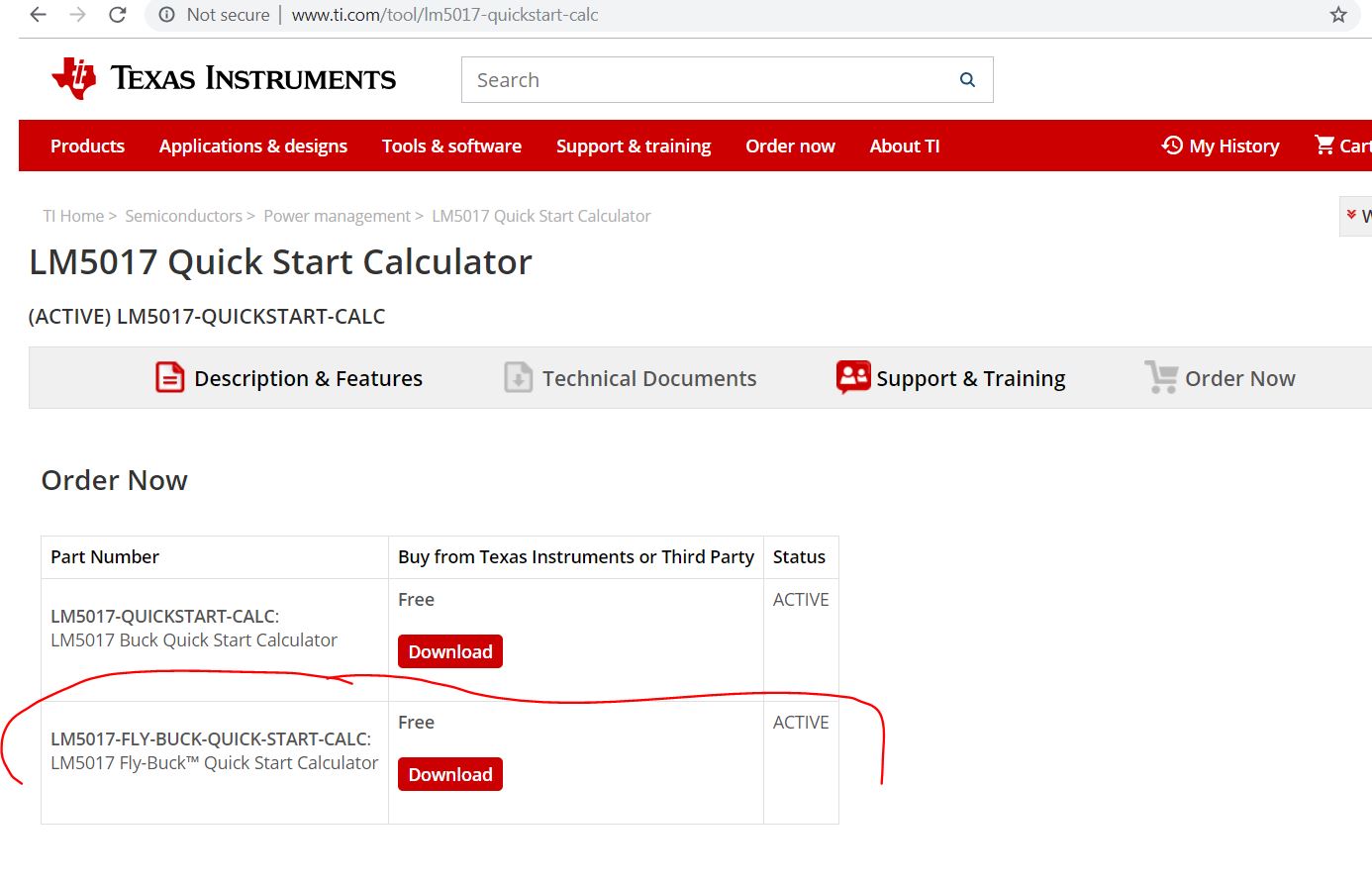
Kindly point me to central repository for latest proven version of Calc xlsx sheet (Tried search in TI e2e as well as google, but all lead to e2e forum only)

One gets to see number of these being shared in e2e forum, appearing with different names, locked & unlocked formats. Few names listed below:

  •  3288.Flybuck Flyback Calculator
  •  Calculator_Rev1p03_result
  •  Calculator_Rev1p03_Flybuck_Boost
  •  Calculator_Rev1p03_Unlock
  • FlyBuckCalculator_snvu445.zip

Besides,

kindly request share the link to background xlsx sheets being used in various formulas

Many Thanks

  • Hello ,

    THe excel calculator can be found  in the product folder  under tool tab . There are two calculators there  ie buck and flybuck calculator :

    ---Ambreesh 

  • Also you may refer to datasheet for all the formulas used int he excel sheet calculator .

    --Ambreesh
  • Thanks Dear,

    Refer said 5017-flybuck transformer sheet, Kindly point me to Literature that elaborates:

    * Cell B30, why add 50% of ΔIL to ILavg ?

    * Cells I29 & I33;   formula used for air-gap to round and rectangular center-leg cores

    Besides,

    * Cell I25, how's this calculated 'μe' different than "μe" in ER9 datasheet i.e.   https://www.tdk-electronics.tdk.com/inf/80/db/fer/er_9_5_5.pdf

    * Cell I10, basis for Bmax value selection ? as above ferrite datasheet doesn't mention such Bmax values

    Best Regards

  • Hello ,

    Please find my response below :

    * Cell B30, why add 50% of ΔIL to ILavg ?

    Ambreesh : That is used to find the peak current to ensure that the peak current is below 0.7A . In a buck converter , the peak inductor curent is Average inductor current(which is Iout) + 1/2 total inductor ripple current .

    You can approach the formula in a different way too as done int he datasheet :

    * Cells I29 & I33;   formula used for air-gap to round and rectangular center-leg cores

    You should be able to get K1 and K2 values from the magnetics vendor and then can calculate the Air gap . 

    Further as mentioned above the Airgap is dependent on AL value chosen and vendor like tdk do provide Al vs air gap chart like the one below :

    * Cell I10, basis for Bmax value selection ? as above ferrite datasheet doesn't mention such Bmax values

    Ambreesh : The ferrite material has below saturation flux density .

    As shown in table , ferrites saturate above 0.3 T thus a value of Bmax equal to 0.28-0.30 T may be selected to maximize core utilization, or Bmax = 0.25 T can be chosen for a more conservative design.

    ---Ambreesh 

  • Ambreesh Tripathi said:

    Hello ,

    Please find my response below :

    [Luck] Dear Ambreesh, many thanks for the response, kindly request your attention to point-wise comments embedded below.

    Very Best Regards

    * Cell B30, why add 50% of ΔIL to ILavg ?

    Ambreesh : That is used to find the peak current to ensure that the peak current is below 0.7A . In a buck converter , the peak inductor curent is Average inductor current(which is Iout) + 1/2 total inductor ripple current .

    [Luck] Agree, all datasheets suggest "ILpeak = ILavg + 1/2 ΔIL". What am expecting is mathematical or graphical justification(derivation) of this very concept, like why not add 1/3 or 2/3 of inductor ripple current !

    You can approach the formula in a different way too as done int he datasheet :

    * Cells I29 & I33;   formula used for air-gap to round and rectangular center-leg cores

    You should be able to get K1 and K2 values from the magnetics vendor and then can calculate the Air gap .

    [Luck] : LM5017 flybuck transformer xlsx, Cells I29 & I33  do not refer any K1 or K2 constants. Rather it uses complex equation comprising of length9(a), width(b) and le/μe ratio numbers only. Rectangular center leg equation "I31*I32/2*(1/I26-(I31+I32)/I31/I32-SQRT(((I31+I32)/I31/I32-1/I26)^2-4/I31/I32))" translates into

    and round center leg equation uses diameter in place of length and width I28^2/2*(1/I26-2/I28-SQRT(1/I26^2-4/I26/I28))

    A. Please share document link for above complex equation.

    B. What are these K constants

    C. Refer link to ferrite datasheet that has these K constants defined

    D. Which document do you refer to quote K constants based formula for air gap below.

    [Luck] Which document used to quote table above? please share the Link !

    Further as mentioned above the Airgap is dependent on AL value chosen and vendor like tdk do provide Al vs air gap chart like the one below :

    [Luck] Which document used for Tabular  details below? please share the Link !

    [Luck] Which document used for Graphical details above? please share the Link !

    * Cell I10, basis for Bmax value selection ? as above ferrite datasheet doesn't mention such Bmax values

    Ambreesh : The ferrite material has below saturation flux density .

    [Luck] Which document used to quote table above? please share the Link !

    As shown in table , ferrites saturate above 0.3 T thus a value of Bmax equal to 0.28-0.30 T may be selected to maximize core utilization, or Bmax = 0.25 T can be chosen for a more conservative design.

    ---Ambreesh 

  • Hello Luck ,

    Sorry for late response .

    * Cell B30, why add 50% of ΔIL to ILavg ?

    [Luck] Agree, all datasheets suggest "ILpeak = ILavg + 1/2 ΔIL". What am expecting is mathematical or graphical justification(derivation) of this very concept, like why not add 1/3 or 2/3 of inductor ripple current !

    Ambreesh : In a buck converter , the average of inductor current is equal to output current as shown below :

    Now if the output current is known , the peak current can simply be calculated as Io+ 50%Iripple and hence hence of ripple is added and not 1/3rd or 1/5th 

    In the case of flybuck , the similar concept is applied ie first total load current is calculated as Iout primary + reflected current from secondary back to primary and then half of ripple is added to get the peak current . 

    Q2-Cells I29 & I33;   formula used for air-gap to round and rectangular center-leg cores

    Ambreesh : This is how i am used to calculate the Air gap  . I am not sure what formula is used in the excel sheet . i will ask the author to see if he can share the source of the calculation on the excel sheet . 

    Here is the reference you can use for this formula from a magnetic vendor :

    https://www.tdk-electronics.tdk.com/download/531516/449506bb84194c3510018ae82f66b4cc/pdf-ecoresgeneralinformation.pdf (page 6)

    and values can be found here :

    http://www.mouser.com/ds/2/400/er_42_22_15-525726.pdf

    Further here is core list and significant design data for most of the core i got from one magnetic vendor : 

    For Al-value vs air gap length please refer to below link :

    https://product.tdk.com/info/en/catalog/datasheets/ferrite_mz_sw_e_en.pdf (page 6) 

    Q3- Cell I10, basis for Bmax value selection ? as above ferrite datasheet doesn't mention such Bmax values

    Ambreesh :  The saturation flux density Bmax or Bs varies with different ferrite material . You can ask for core specification and ferrite specification from magnetic vendor . Here is the link to typical ferrite core specification from TDK having info about Saturation flux density . 

    http://www.mouser.com/ds/2/400/er_42_22_15-525726.pdf

    ---Ambreesh