This thread has been locked.

If you have a related question, please click the "Ask a related question" button in the top right corner. The newly created question will be automatically linked to this question.

LM5175EVM: what are D1, D2 for LM5175EVM

Part Number: LM5175EVM
Other Parts Discussed in Thread: LM5176

Dear Sir,

I have some question for LM5175EVM as attached file.

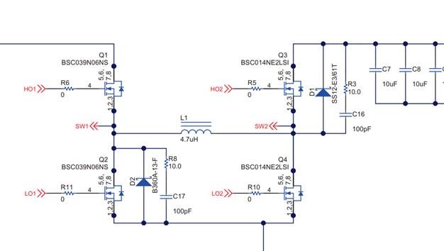
1. Why it use D1, D2 for reference design. could you explain usage of D1, D2 as below picture.

I think it seems free wheeling diode..

2. Can I remove the D1, D2 there are any affect?

  • Hi Dexter,

    Just let you know that we are reviewing this and will get back to you in two days.

    Thanks,
    Youhao Xi, Applications Engineering
  • Hi Dexter,

    Thank you for considering the LM5176 in your applications. You are correct that D1 and D2 are "freewheeling" diodes. They are used to bypass the MOSFET body diodes which are usually slow, having higher forward drop, and larger Qrr.

    The high side and low side FETs on one switching legs must have dead time, otherwise there will be a direct short path to ground. During the dead time, the inductor current must continue to flow. Adding a small Schottky diode will help prevent the use the body diodes during dead time, and hence improve efficiency, and reduce the possible ringing due to body diode's Qrr.

    In the real application, these external diodes are good to have but not must to have. You can choose not to use them. My suggestion is, reserve the positions on your PCB, then you have the backup option to use them if needed. Otherwise you will have to redo your PCB.

    Thanks,
    Youhao