


Other Parts Discussed in Thread: TPS62147, TPS62170
Dear TI,
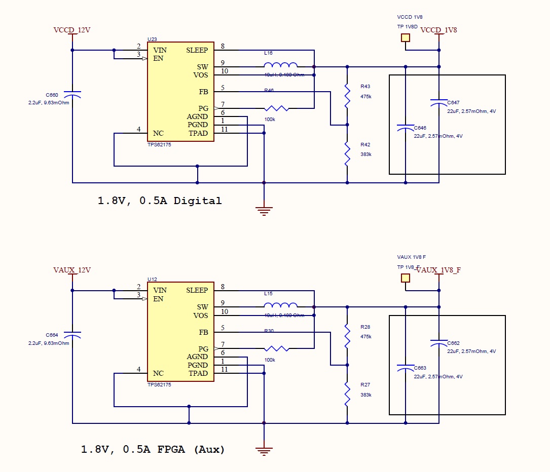
I designed and made a PCB board with dua TPS62175 in the PCB board.
Both are designed to generate Vout of 1.8V.
I used Webbench for the design.
One Vout (VCCA_1V8)_F is used for auxiliary and one (VCCD_1V8) for main.
Both circuit are same in design and used same parts.
The Vout for main produces 2.12V output instead of 1.8V, but the vout for aux produces 1.8V as designed.
PCB layout for both power is almost same but produce different volatge.
I measuered Vout and VFB for VCCD_1V8 output and the results are follow:
Vout = 2.12 V
VFB = 1.14 V
In the datasheet, typical volatge for FB is 0.8V, but the VFB for VCCF_1V8 was measured around 1.1 V.
I tried to change R1 and R2 (voltage divider register values), but VFB and Vout did not changed significantly (almost no change).
Cloud let me know how to make the Vout to 1.8V ?
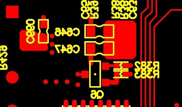
the followings are PCB layouts:
1. Overall layout for VCCD_1V8 (the one that measued as 2.12 V)

2. Bottom layer of VCCD_1B8

3. VAUX_1V8_F (Vout that works correctly)

Best Regard.

