Because of the Thanksgiving holiday in the U.S., TI E2E™ design support forum responses may be delayed from November 25 through December 2. Thank you for your patience.

This thread has been locked.

If you have a related question, please click the "Ask a related question" button in the top right corner. The newly created question will be automatically linked to this question.

LM809: Lm809

Part Number: LM809

Hi I have two questions.

First  it's possible to put to ground ic output with npn transistor? I think it's necessary to put a resistor in series of collector to don't load the ic output. I see a schematic where npn is connected directly to ic output

And ground, this can damage ic?

Second. I see in schematic a pull up resistor of 100k V is 3v3. In datasheet say for lm809 tu put pull down resistor on output. Can you explain if is correct to pull up output and why?

Thanks

Paolo

  • Hi Paolo,

    1. Can you share the schematic?

    2. What output topology do you plan on using for the device? (active-low/active-high)?

    3.  If there is a low impedance path through either the low-side or high-side output driver stage (with a voltage across), this could cause damage to the device. We specify the maximum output current the device  can sink/source as 20mA, so keep that in mind when designing your circuit.

    4. The schematic you are talking about for attaching a pull-down to the output is attached below for convenience. This pull-down is necessary to mitigate the output "glitch" associated with when the device is below its minimum VCC spec of 1V. When the device is below its minimum VCC spec, the output stage is undefined, thus can drift upwards. To ensure that this does not trigger or disrupt anything downstream from the output, a pull-down is recommend to keep the output at ground. Here is a resource if your interested in learning more about this phenomena associated with all modern supervisors http://www.ti.com/lit/an/snva845/snva845.pdf

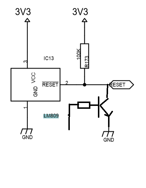
  • This in part of schematic i tell you. I think there are 2 mistake, first 100K in this scheme is pullup (in datasheet say pulldown for reason you explain). Second NPN put in short the output of LM809. My question is 100K on pullup is really a mistake? i think who design this scheme want to drive more device without buffer the reset signal...  second and obvious NPN damage the IC or is short protected ? i think is better idea to insert resistor on collector of transistor.

    Thanks

  • 1. The 100k pull-up does not make sense to me on why it would be needed for any use-case.
    2. The device does not limit output current. If you reset is high, and you ground the output, the device will get damaged.
    3. Base resistance should be fine as you can limit the collector current, assuming you can bias it up correctly. You just need to factor in the load current on the device (what else it will be driving) . We specify the maximum output current the device can sink/source as 20mA, so keep that in mind when designing your circuit.