This thread has been locked.

If you have a related question, please click the "Ask a related question" button in the top right corner. The newly created question will be automatically linked to this question.

UCC38C43: Buck Boost output current 0 to 10 Amp

Part Number: UCC38C43

Hello friends,

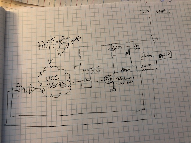
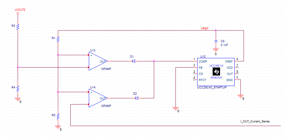
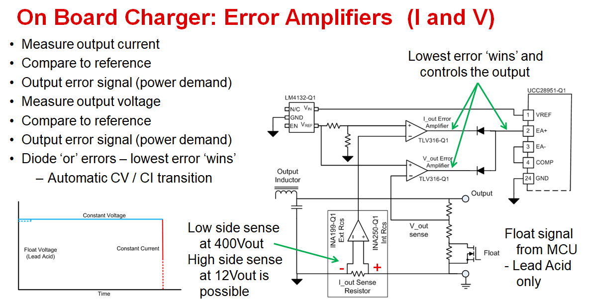
I was wondering if anyone can help come up with the appropriate TI parts to design a simple Buck Boost using the UCC38C43.

input : 12 to 30 VDC

Output: 0 to10 Amps

3 segment display with a divide by 10 switch to display mA.

Rotary encoder for accurate D/A output current control. 

If there is a TI reference design I can go by, that would be great.

With best regards,

Alfred

  • Hello Alfred
    There is a lot of technical design information on how to use the UCC38C43 on the product page at www.ti.com/.../technicaldocuments. This part does have a model in the Webench s/w which you can access by clicking on the tools and software tab on the product page www.ti.com/.../toolssoftware Webench will generate an initial design that you can work with.

    I'm afraid I cannot help you with the other parts of your question - a 3 digit display and the rotary encoder. I'd suggest you post these questions in one or more of the other e2e forums -

    Regards
    Colin
  • Hello Collin,

    Thank you so much for the information.  I got a reference design and it looks like it is what I am looking for.  Do you know if there is a way to put three of the reference design on one board?

    I also need to tap into the output current control.  

    LM5118Q1MH/NOPB 12V-30V to 12.00V @ 10A
    Design: 7
    Topology:
    Buck_Boost
    Date Created:
    4/3/2019, 9:43:33 PM
    Date Modified:
    4/3/2019, 9:43:33 AM
    Best regards,
    Alfred

  • Hello Alfred

    My apologies for the delay in getting back to you.

    I don't know which reference design you mean but in general it is always possible to put multiple copies of a schematic onto a single PCB.

    I don't understand your question - can you explain a little more about what you mean by 'need to tap into the output current control'

    Regards
    Colin
  • Hello Alfred

    I'm marking this thread as 'resolved' but if it is not then please provide an update here and I'll continue to work with you on this.

    Regards
    Colin
  • Hello Colin,

    Thank you so kindly for your reply.  I was stationed out of town for 10 days and could not reply back.  I worked off of the workbench and I could not get a current limiter configuration to come up.  I saw switching flyback power supplies and buck/boost configurations.  I wanted to know how I can configure the UCC38C43 to output Adjustable current via the negative leg out of a N channel MOSFET.  See attached sketch.

    I appreciate any help.

    Alfred

  • Hello Alfred

    My apologies for not replying to you earlier. I think you are trying to develop a PSU with a constant current output and this can be done with the UCC38C43 as shown here. Tying FB to GND will cause COMP to default high and the two OPAMPs act as error amplifiers and can pull COMP low to modulate the voltage at the pin. The COMP pin is essentially a current demand signal into the PWM comparator. The data sheet shows the COMP being used in this way in Fig 29 (Typical Offline Application)

    This is a variation on the scheme shown in the second image below and will give you a CI characteristic with a Voltage limit.

    Please let me know if you need any more information.

    Regards

    Colin

  • Hello Alfred

    The images didn't attach to the post even though they were CLEARLY VISIBLE when I pressed the POST button -

    Regards

    Colin

  • Hello Alfred

    Third time lucky - I hope

  • Hello Alfred

    Maybe the fourth time :-)

    If the images are not visible then please send me an email and I'll forward them on to you. I'm at colingillmor@ti.com

    Regards

    Colin

  • Thank you Collin. I will pursuethe design en-light of the information you provided.

    Best regards.