Other Parts Discussed in Thread: UCD3138
Hi,
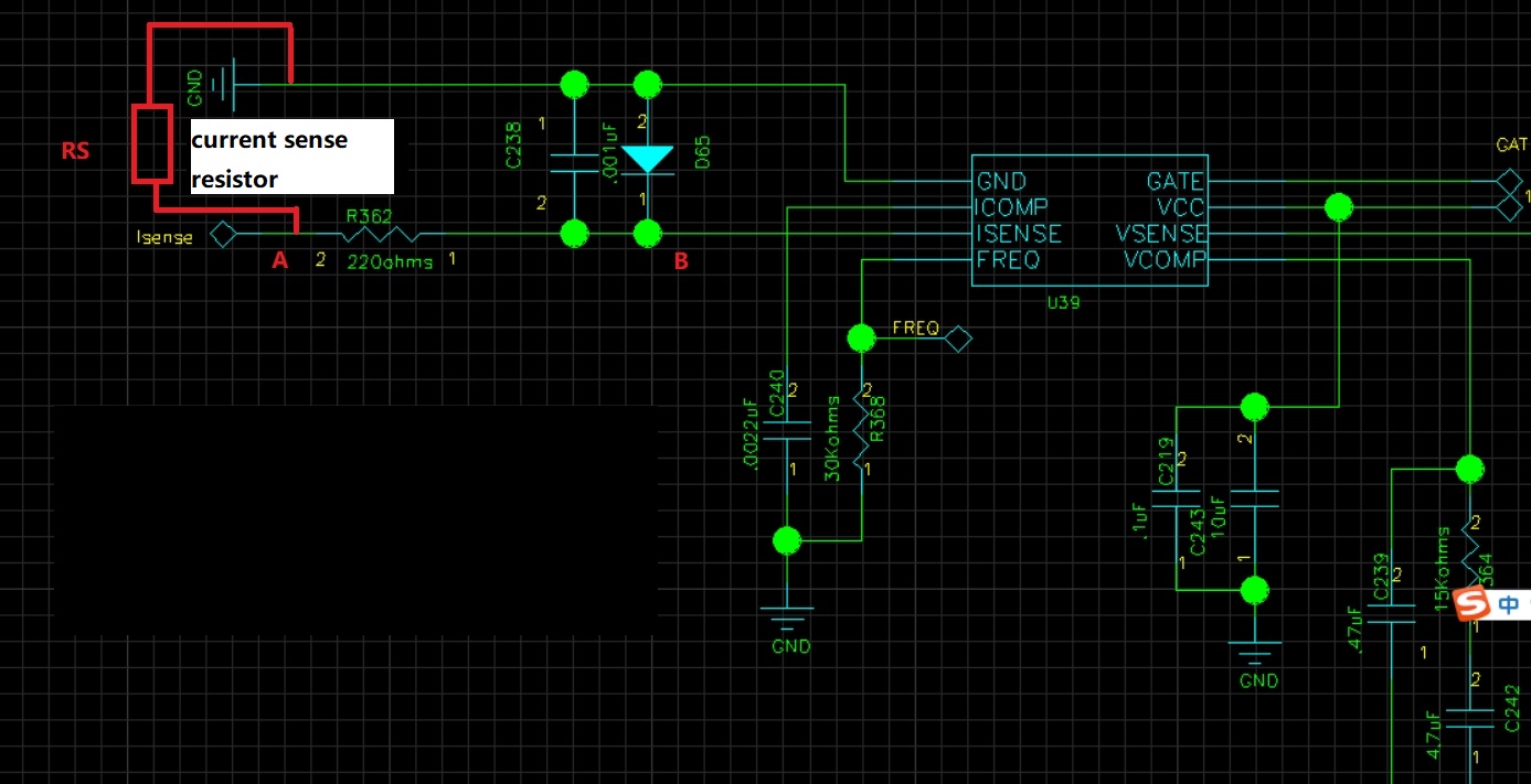
my customer is using UCC28180 to build a 7kW PFC. The input is 230V AC and output is 400V. The input current limit is 32A.
They want to test the current loop bode plot of PFC.
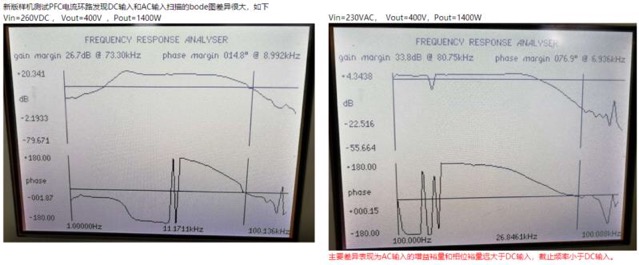
They tested with 260VDC input or 230VAC input, 400V DC output.
At 1400W power load (still in continuous current mode), the bode plot is quite different with 260VDC input (left in the picture) and 230VAC input(right in the picture).
Phase margin is 14.8°, gain margin is 2.19 for the left picture, which means the margin is not enough(>6db, >15°).
But in the right picture, the margin is enough.
At 2800W power load, there is less difference between the bode plot with 260VDC input (left in the picture) and 230VAC input(right in the picture). Both shows enough margin.
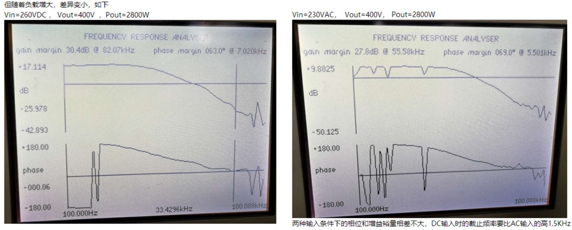
As the load gets heavier, the bode plot difference between DC input and AC input gets smaller and smaller.
The question is whether should I use DC input to measure the bode plot of PFC or AC input? Why the bode plot at light load is so different with DC input or AC input.
If DC input should be used, what's the voltage level should I use because in real application the input is AC.