This thread has been locked.

If you have a related question, please click the "Ask a related question" button in the top right corner. The newly created question will be automatically linked to this question.

BQ24780S: BQ24780S EMI issue

Part Number: BQ24780S

Team,

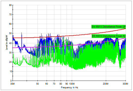
Customer found EMI issue when testing BQ24780S. It seems that it is caused by swtiching frequency 800kHz. EVM test result is better than customer system, but it still failed. Customer board PCH is 2 layers. Do you have any recommendation of how to improve this? I am assuming that EVM should be able to pass EMI test, right?

1. Customer system test result

2. EVM test result

  • Hi Nic,

    There is no "one size fits all" answer for EMI, but here are a number of things that your customer can try to improve their EMI performance.  They don't need to do all of it, but I wanted to list the various options so that they can choose the method that will work best for them.

    1.  Slow the switching frequency from 800 kHz to 600 kHz. 

    In addition to shifting the EMI frequencies, the overall EMI is generally reduced when the switching frequency is reduced.  This probably won't have enough of an effect by itself to get them through certification, but all it takes to do it is to flip a couple of bits in register 0x12, so it is a good starting point.

    2.  Metal shield/can

    The main negative to this approach is cost, but it is very effective at shielding EMI with no reduction to power efficiency.

     3.  Filter caps

    You can reduce EMI greatly by adding a 0.1 uF and 0.01 uF ceramic capacitor as close as possible to the High-side switching FET.  A pretty good "ballpark" estimation for ceramic filter caps is that a 0.1 uF ceramic cap should filter out ~10-50 MHz very well, a 0.01 uF capacitor should filter out ~30 – 200 mHz.  You really need to look at the datasheet though, and keep in mind that voltage derating can move these filter frequencies quite a bit.

    3.  Slow down the turn on/off of FETs

    Both the high-side and low-side switches can contribute to EMI, so potentially this needs to be applied to both FETs, but the high-side FET tends to have larger contribution to EMI, so if only done to one or the other, choose the high-side FET.  This can be done either by inserting a resistor between the gate drive and the FET gate or by putting a parallel capacitor from the FET gate to source.  For the Low-side FET, a parallel capacitor is the better option because the "Miller Effect" or "Miller Capacitance" (drain to gate capacitance) can sometimes cause the gate voltage to rise and turn on the low side FET (this is rare BTW), and a parallel capacitor from G-S helps to combat this, so you get "two birds for one stone."  

    4.  Add a snubber circuit to SW node

    The snubber works by absorbing high-frequency ringing at the SW node.  The resistor and capacitor values generally need to be determined empirically.  When empirically tuned to a given application, it can be very effective at removing EMI, but can have a significant impact on performance (~1-2% efficiency drop.)  If they choose this approach,  SLVA255 is a good reference for determining appropriate R-C value.


    I would say that the order of effectiveness of these approaches is:

    1. Metal shielding is very effective and without impact to performance, but it is the most expensive solution

    2. Snubber circuit on SW node second most effective and relatively low cost, but with significant (~1-2%, but it is highly dependent on component values) impact to efficiency.

    3. Slowing the turn on/off of the FETs.  As with snubber circuit, this component value pretty much needs to be empirically tuned to the application.  Usually this will have a little less reduction on efficiency (~0.5-1%) versus the snubber but may also be less effective.

    4. Adding filter caps can be very effective if done right.  I am listing it a little lower than slowing the FETs in effectiveness simply because each filter cap only filters out a range of frequency, whereas showing the FETs will reduce EMI across all frequencies.  But this is a great first step (or even preemptive step when building schematic) because it should have a fairly low impact on efficiency.

    5. Reducing SW frequency from 800 kHz to 600 kHz.  Slowing the switching frequency should improve the overall EMI, but it is generally only a moderate improvement.  And the good news is that slowing the switching frequency actually improves efficiency (although it will increase ripple and may have slightly negative effect on transient response.)


    Regards,

    Steve

  • Hey Steve,

    It is really amazing to hear from you here! Thanks for all the detailed suggestions and I will let customer try the approaches. Appreciate it!

    Regards,

    Nic