This thread has been locked.

If you have a related question, please click the "Ask a related question" button in the top right corner. The newly created question will be automatically linked to this question.

LMZ20502: Strange Phenomenon

Part Number: LMZ20502

Dear sir or madam 

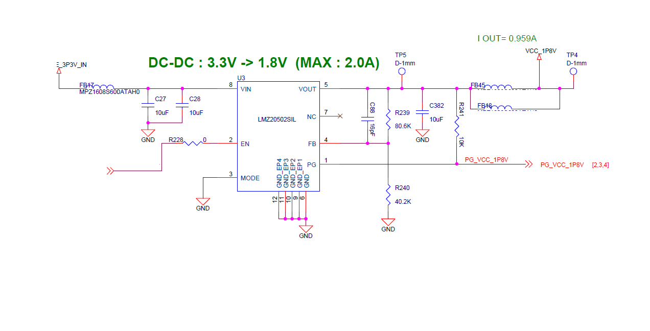
I have a problem with LMZ20502  in my board. The schematic is below.


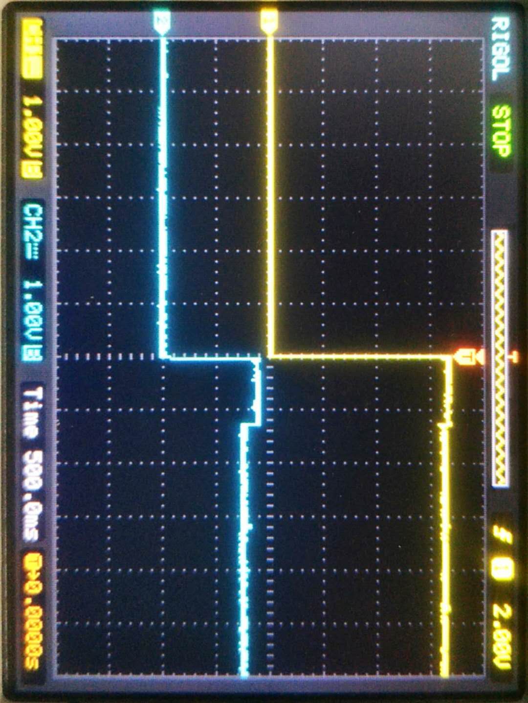
While , After 3.3V powered up  and chip enabled  , I could see the 1.8V output from a multimeter  in a very short time  , and then it turned to 1.5V . And the load couldn't work well in this voltage .

If I inserted a multimeter in  current  instead of  two beads .  Then , It could work well as 1.8V . As I saw , The current to the load is about 1.3A . 

I am confused about this phenomenon . 

Can you give me some advice ?

Thank you in advance.


  • Hi,

    Can you provide a oscilloscope waveform for VIN,VOUT,IOUT, and EN? I'd expect your output voltage regulation should look similar to Figure 22 Blue Trace

    Looking at your schematic, the component values follow the typical application values found in Figure 16.

    How many of your boards experience this failure phenomenon? 

    Regards,

    Jimmy 

  • Hello , Jimmy 

    There is only one board  with this issue . 

    All the others are OK  at present .

  • Hi,Jimmy

    Actually ,
    When I welded a 25mm wire instead of beads FB45 FB18 ,
    The voltage on TP5 was about 1.7V , whereas on TP4 , it was 1.45V .
    As I mentioned before , The load current is about 1.3A . And LMZ20502 can afford 2A current , So , that's the point.

    Thank you
  • Hi,

    Have you tried to swap the known bad board's LMZ20502 with a new power module? Again there is no issues schematic-wise. If the issue still persists, can you tell me the ferrite bead part number and the DCR of it? Even at full loading (2A) the output voltage for a 1.8V application should look like Figure 22. In your case for a 3.3V to 1.8V conversion at 1.3A loading the output voltage is expected to drop to 1.795V with a minimum of +/- 1% deviation simply based on the feedback resistor tolerance. This you have only one board that exhibit this phenomenon, I suspect the power module might be damaged from EOS, hence I'd recommend replacing it with a new one to check if the board still functions as intended. 

    Another question for quick confirmation, is your power supply current limited during operation at 1.3A loading for the bad board?

    Regards,

    Jimmy

  • Hello , Jimmy

    I've already replaced the LMZ20502 with a new one , but  it still doesn't work .

    My bead part number is MPZ1608S600ATAH0 , which DCR is 20mOhm .

    Actually , The other boards are working well .

    Thank you all time 

    best ,

    Anglic

  • Hi,

    Thank you for the reply. The ferrite bead looks normal. Even with 20mOhm DCR at full load(2A)  the output voltage should not drop by more than Iout x DCR(bead) = 0.04V. Also you said that replacing the LMZ20502 with a new one didn't solve the problem, this makes me wonder a few things.

    1. When you tested your boards, was the setup identical between the working boards and the single failing board?
    2. What type of loading (e-load or resistive) are you using? Is the output voltage stable at 1.8V if not connected to the load? 
    3. Have you tried removing FB45 and FB48 from the board and retesting the single failing board to see if 1.8V output is stable at full loading?
    4. Can you provide the PCB layout? 

    Regards,

    Jimmy 

  • Hello Jimmy

    Thank you very much .

    1. The setup was the same .

    2.  The Lmz20502 supplies to FPGA . The Lmz20502 can output  stable 1.8V  if not connect to the load .

    3.  After removing  FB45 and FB18 , the LMZ20502 output 1.8V which is stable . 

    4.  I am not sure if it will be helpful . 

    sincerely ,

    Anglic

  • Hi Anglic,

    It would also help if you can provide the waveforms for the failing condition. Please probe VIN, VOUT, IOUT, and SW. You can access the SW node by probing the one-side of the exposed inductor on top.

    Regards,
    Jimmy
  • Thank you , Jimmy

    I post the waveform of  Vin and Vout here , 

    While the yellow line is Input , and the blue line is output , 

    As we can see , there is a clearly drop after  a  real time .

    Sincerely .

    Anglic

  • Hi Anglic,
    Could you please also measure the load current and show the SW node waveform?
    Cheers,
    Denislav
  • Hi Anglic,

    Were you able to resolve your problem? If not can you able to provide the load currents and SW node as Denislav mentioned?

    Regards,
    Jimmy
  • Hey , Jimmy

    Sorry for replying  you so late . While , at present , We don't have the probe to get the current change information . 

    I'm trying to figure out a feasible approach.

    Thank you 

    sincerely

    Anglic

  • Hey Denislav

    Thank you for your concern and sorry for replying to you so late .
    It's a shame that we don't have a proper probe to measure the current .
    Thank you all the same .
    Once we have the data about current , I'll post it here .
    Thank you again

    Sincerely
    Anglic
  • Hi Anglic,

    I will be closing this thread for now. When you get the scope probe measurements, please post them in a new separate thread so that we can continue the discussion from there.

    Regards,
    Jimmy