This thread has been locked.

If you have a related question, please click the "Ask a related question" button in the top right corner. The newly created question will be automatically linked to this question.

LM431: LM431

Part Number: LM431

Hi TI team,

We're using LM431 in a Crowbar OVP circuit. We have been facing something strange in this use case of LM431; it is that initially the crowbar was triggering way above the designated threshold and consequently we made changes in the resistor divider circuit that defines the threshold for LM431, At this point of time the crowbar seems to be working fine but whenever we try to measure the reference voltage being received by LM431 using multimeter it triggers the crowbar, even though the supply is 5V.

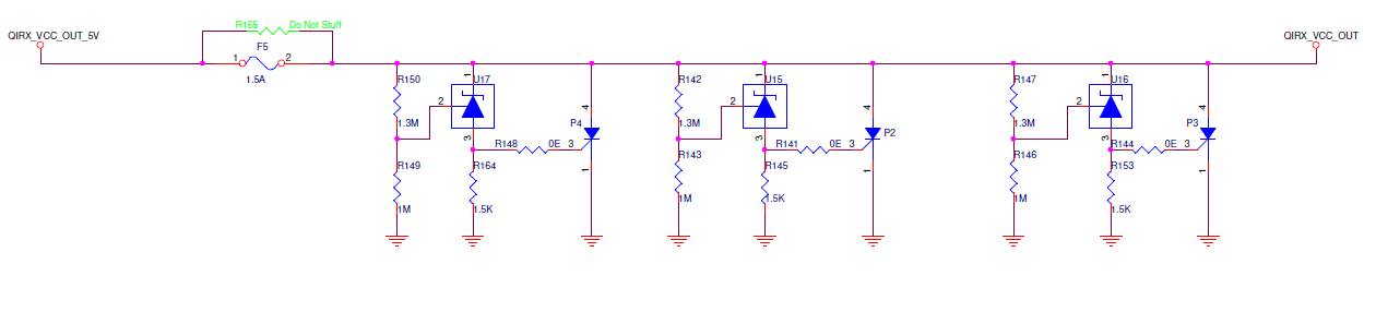
Below is the circuit: Version 1


Version 2: Modified resistor divider.

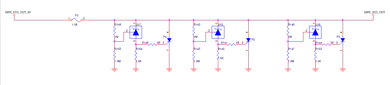
With version 1, the OVP was triggering at around 7V and with version 2 it is triggering at 5.7V.
But as stated above the OVP triggers whenever we try to measure the reference voltage of LM431.
Could you give us some insight on the cause of this?
Thanks,
Abhinav

  • Is the multimeter you are using is configured in high-Z mode? What is the input impedance of the multimeter?
    For example, a typical benchtop multimeter datasheet's input impedance is 1Mohm. So if you are measuring the reference voltage with a "normal" termination you are essentially having the equivalent resistance from the reference pin to ground, changing the VKA of the LM431.
  • Hi Marshall,
    I understand your point that this triggering could be the reason of loading effect of the multimeter but irrespective of the input impedance of the multimeter I should observe only incorrect reference voltage reading. Shouldn't that actually happen? If the multimeter has higher input impedance than 1.3M( used in resistor divider) I should observe a more accurate reference voltage and in case the multimeter has lower input impedance (if we take typical 1Mohm ) the loading should only decrease the net impedance seen by LM431 and hence lower voltage reading on multimeter.

    Another catch to this triggering phenomenon is that I do not observe this issue if I measure it on oscilloscope that uses probes of 1Mohm input resistance.


    Thanks
  • 1. Doesn't the voltage reference's voltage have a direct effect on the trigger point? My understanding of the circuit is that it does?
    2. Is the trigger point correct with both revisions of the circuit when not measuring anything(besides the output)?

  • My response:

    1. Yes it does.

    2. As mentioned that in version 1 the input voltage that triggers the crowbar is 7V and in version 2 the input voltage that triggers the crowbar is 5.7V. I am measuring only input and output in such case nothing else.i.e QIRX_VCC_OUT_5V and QIRX_VCC_OUT.

  • So you are triggering at the wrong point when measuring with your DMM? We both agree that the voltage reference voltage has a direct impact on the trigger point, as well, a measurement device will have an effect on the equivalent resistance on reference pin if being measured.

    You do not see the same issue when measuring with your oscope, which has a different termination? Doesn't this point to your measurement technique causing this circuit performance?
  • Marshall I am not entirely sure that you're getting my doubt right. And to answer your questions:

    Yes the circuit triggers even at 5V if I try to measure the voltage reference of LM431 using DMM, when it is designed to trigger at 5.7V. It triggers even I touch that particular point(reference point; R150) with bare hands or even anything.

    It seems the reference point is sensitive to anything external touching it.

    The circuit behaves as its designed to when that reference point is left untouched.

    I hope you're getting what I am trying to convey.

  • Hi Abhinav,

    Both mechanical and thermal stresses put on the device will effect the voltage of the reference
  • Please let us know if you need additional help.
  • Alright Marshall!

    But this doesn't yet clarifies why LM431 would get activated when measuring reference voltage with DMM and not with oscilloscope.

  • It sounds like there is a difference in either measurement technique or measurement influence when measuring with the oscilloscope. If you believe that the terminations are equivalent between the DMM and oscillscope, how about you try soldering very thin gauge wires (ie:30AWG) to the measurement points, tape down the wires w/ kapton tape, and then clip on your probes. This should minimize the amount of mechanical stress you could be possibly putting on the circuit area. This could especially been a problem if you were apply the oscillscope probe with the pogo pin directly, where you would be putting a whole lot of force over a small area.

    It would be helpful to a get better understanding for your test setup and technique.