This thread has been locked.

If you have a related question, please click the "Ask a related question" button in the top right corner. The newly created question will be automatically linked to this question.

Current limiting mode

Part Number: TPS2492EVM-003
Other Parts Discussed in Thread: TPS2492

Hi TI Team,

I have a problem with turning mosfet off in current limiting mode.

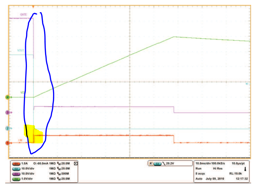
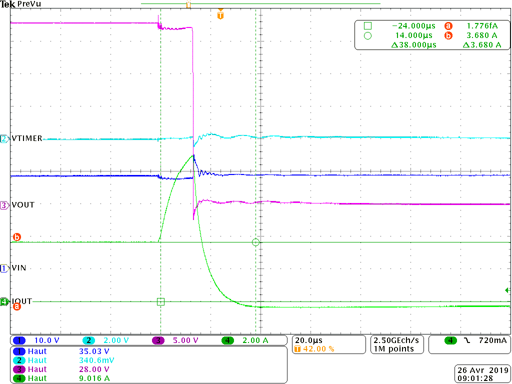
I am using the evaluation board TPS2492EVM-003 with some differencies : Vin=28V, Rsense=10mOhm, Ilim=5A, and I disabled UV and OV protection (i.e without R5 on the demoboard).

I start on the board with a load such as Iload< Ilim, everything is ok, output current is ok, mosfet is on, output voltage is 28V(=Vin). Then, I modify the load, Iload>Ilim.  At this moment, a strange behaviour occures.

TPS2492 doesn't enter in current limiting mode as soon as Iload >Ilim, but Iout rises to 9A whereas Ilim=5A, then Vout falls to 0V and the fault timer doesn't start. Why the fault timer doesn't start as soon as Iload>Ilim ?

Then, whitout any action on the enable input, the component restart and turn the mosfet off normaly at Iload=5A.

I tested the case with different input voltage levels, and it is not happening when Vin<22V. I recall I have disabled UV and OV protection.

The first two pictures reprensent the same occasion but with different time/div. The last one, represent the cas where Vin=20V.

I don't understand why the fault timer doesn't start normaly for Vin>22V and why the component restart after ?

Thanks in advance for your help.

Best regards.

  • Hi Zakya,

    Welcome to E2E!
    I will look into this and get back to you

    Best Regards,
    Rakesh
  • Hi Zakya,

    In the first test case (figure-1), the load current is changed fast so the controller treated as short circuit and cut-off the output. The controller again gracefully starts in current limit mode (figure-2)

    Can you slowly increase the load current to emulate overload situation and check ?

    Best Regards,
    Rakesh
  • Hi Rakesh and thank you for your answer.

    I checked the situation by slowly increasing the load like you advised me.
    Indeed, you're right, the controller behaves properly, cut-off the output and doesn't restart anymore.
    But, I still have a question, when I apply a hard short circuit (the load current changed faster), why the controller doesn't behave like the datasheet ?(cf figure 15 page 16). Why does he restart again ?

    Thank you
    Best regards,
    Zakya
  • Hi Zakya,

    For short circuit, the device switches OFF immediately and turns ON again in power limit mode. Your second test waveform response is similar to Fig 15 page 16. Only timer period is different. Increasing CT value will give similar response.

    Best Regards,
    Rakesh

  • Hi Rakesh,

    May I understand the behaviour in my second test waveform is the normal behaviour of the component when applying hard short circuit ? that is to say switch OFF immediately with an output current higher than my limitation and turns ON after with correct cut-off ?

    Sorry but for my part, I see some differences between the figure 15 page 16 of the datasheet and my second test waveform.
    In the datasheet, when the short circuit is applied, the timer immediately starts (like in my third test waveform), and Vout never increases once it fell contrary to my case (second case). The fact that Ct is weak could explain this restart ?


    Thank you,
    Best regards.
    Zakya
  • Hi Zakya,

    The variation in Vout is due to the difference in the impedance of the short. figure 15 has perfect short circuit whereas your test scenario resembles having 2.4Ohm short.

    Zoom-in the highlighted portion in below will match to your timer start behavior.

    Best Regards,

    Rakesh